
Armored Cable length varies between 122 and 1800s because distance between Ign Sw and Ign Coil is different [Any 12V544 owners reading this are invited to measure their Armored Cable and report this to the author. TIA!]
...more Volvo Armored Ignition and Key Stories!
"...drill out the lock!"
Nov 2025 R. Kwas (updated continually) [Comments added]
Reference Information
Volvo Armored
Ignition System, Electrical Checks
Replacement of a
Volvo Armored Ignition Coil Assembly
Collateral Damage
Lock Cylinder
Installation
---------------------------------
Background:
I recently had to "drill out" a 122 Ignition Lock Cylinder, for a gentlemen who lost
his primary Ign Key and couldn't locate his spare...he had finally given up all
hope of being able to operate the Ign Sw with a key but needed to be able to
start the car which had been parked for a couple of months...[my
first and strongest suggestion was for him to expend significant effort to try
to locate the key(s)] after speaking to
him, I finally accepted the job and site visit (not too far away), and advised
the first option would be to try and pick the lock...
Result of my (almost successful!) lock picking efforts:
I was able to lift four of the five pins (I could hear them drop when I released
the tension wrench...damn, so close, but no cookie!)
[Reference Info:
LINK: Picking a pin lock], but try as I might, I couldn't pick the
last pin (I did try my homemade picks and rakes of varying shapes). I guess I'm not such a good lock
picker! I also advised and suggested, before my visit, for him to order a new replacement LC,
which would then be available to replace the removed, keyless LC, and which would obviously come
with two new keys...
After giving up on trying to pick the
lock, getting the owner's
approval/permission, and as much as I hated to do it (I always advise against this, fearing collateral
damage!), I got his OK to "drill the lock" using a Makita cordless turning a shorty 1/4" bit ...which wasn't simple since a drill is squarely blocked by the
Steering Wheel...the process was: Drill (slanted upwards to clear the Steering
Wheel and into the lock pin shafts, trying to defeat these), insert a flatblade
screwdriver and try to turn the Lock Cylinder, drill some more (but not too
deep!!), try to turn it again until the AMP Indicator comes ON...lather, rinse,
repeat until the LC could turn.
When I finally got the LC to turn, it was sluggish against the pin debris still
in the works, but I was able to with the appropriate contortions, flashlight in
the mouth, and diddle-screwdriver behind the Dashboard,
depressing the Retention Pin, to extract the mortally
wounded old LC. I'm liking this operation less and less...!
Upon installing the replacement LC, which I had prelubed well with
Tri-Flow and checked for smooth
operation, once installed into the Ign Sw, I found it very difficult to REMOVE
the Ign Key...upon closer inspection, the reason for this was, I had damaged the hole for the Ret
Pin in the many turn attempts with the flatblade, to such an extent that the Ret Pin was now sloppy and this was
allowing it to interfere with a smooth key withdrawal, even when the key was
vertical...[there's that damn collateral damage I always warn about!], and give as
the prime reason AGAINST "drilling out the Lock", and now I, had a first-hand
demonstration and experience of it...!
The next step was to replace the entire Ign Assy at this
point... I contacted one of my used part resources: Chris Horn [agent_strangeloveAThotmailDOTcom]
Chris supplied a used assembly from a functional car/organ donor, which was installed.
This documents the process and noteworthy milestones.
--------------------------
The Ignition Coil/Armored Cable/Ignition Switch Assembly of 544, 122, and 1800 Vehicles. (Armored Cable length, and therefore Part Numbers vary as a function of chassis).
Armored Cable length varies between 122 and 1800s because distance between Ign
Sw and Ign Coil is different [Any 12V544
owners reading this are invited to measure their Armored Cable and report this
to the author. TIA!]
Ignition Switch internal Connections and Function:
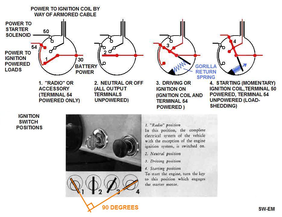
Ignition Switch, Rearview, with feature identification.
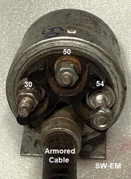
OE terminal hardware is 8mm(9/32").
Ignition Switch, Frontview (Lock Cylinder removed, slot with central Compression Spring for Tailpiece is visible). It is against the counter-force from this CS, that the LC Tailpiece is inserted. The CS is NOT the Gorilla Spring which causes Ign Key fatigue and breakage!

This is NOT the Gorilla Spring you were looking for!
Rearview of Lock Cylinder with Key positions marked. Ign Key is inserted and in Pos 3 allowing Ret Pin to be depressed. Note the total Key swept displacement is 90ş,while the LC Tailpiece sweeps through 135ş! This is a big contributing factor to the key fatigue issue as discussed here: LINK

Ignition Switch with Lock Cylinder test-installed off the vehicle. Retention Pin is clearly visible protruding from the hole in securing ring.

Volvo Armored Ignition System, Electrical Checks:
In typical ignition coils in American and other vehicles, coil Resistance checks would involve the (+) terminal which supplies the coil primary with ignition power (this is also the terminal to which one would connect Batt power to "Hot Wire" that car) , but since there is no such terminal on the Volvo armored ignition, we must connect to this node, to perform electrical tests, in an indirect (but still valid!) manner. We can measure Ign Coil Primary and Secondary Coil Resistances, by simply connecting to Term 30, and placing the Ign Sw in Ign ON Pos3 (using Ign Key if LC is in place, or simply a flatblade screwdriver if it is not, see also above!).
Note: While this is being shown below stand-alone and out of the car, there is no reason this test couldn't be performed with the assembly installed...just be sure to disconnect the vehicle Batt to prevent sending Voltage into your Ohm meter!
Note also: A third test of the Ign Coil Secondary could also be performed...by measuring Resistance between the Coil (-) Neg and Hi-V Terminals.
Acceptable practically measured values should be within 10%.

Primary and Secondary Coil Resistance tests on the Volvo armored ignition
system.
Test 1: Primary Ign Coil Resistance: Terminal 30 to Ign Coil Neg: 3.5 Ohms.

Test 2: Secondary Ign Coil Resistance: Ign Coil Neg Terminal (or as seen here, to Ign Sw term 54) to Ign Coil High V Terminal: 9.2k Ohms

As a point of information and comparison, the Volvo Armored Ign Sys is a Ballast-LESS system (See also: LINK ), so Ign Coil will typically exhibit a Primary Resistance of around 3.4Ohms, (similar to a Bosch Blue Ign Coil). This differs from ign systems with ballast resistor of other car manufacturers, OR for instance, the later 140 series, OR those used with electronic ignitions, where the Ign Coil Primary Resistance is typically in the range of 1.5Ohms).
Replacement of an Volvo Armored Ignition Coil Assembly:
After cleaning up and giving the Ign Coil a new coat of black paint, it was exchanged for the damaged assembly. Highlights of the process:
1. Disconnect Battery.
2. Remove the 2 wires, and loosen 2 securing bolts, at Ign Coil.
3. Remove Lock Cylinder in the normal manner
(Link:
https://www.sw-em.com/ignition_switch_key_breakage_tech_article.htm#lock_cylinder_removal
).
4. Using an 8mm(5/16") nutdriver, remove all wires from the back of the
Ign Sw (note color codes and to which terminals they are connected).
5. Remove 2 screws securing Ign Sw to lower Dashboard.
6. Extract the assembly through the hole in Firewall and out into engine
compartment. As a two-man operation, a helper, safely guiding the assy
into the engine compartment, while routing the Ign Sw past obstacles under the
dashboard works well.
7 Replace the assembly in the reverse order. Again, a helper
working on the engine compartment side, supporting and safely guiding the heavy Ing Coil, while
guiding the Ign Sw under the Dashboard into it final resting position, is highly
recommended!
8. Reconnect all wires to the same terminals on Ign Sw and Coil, from
which they were removed.
9. Reinstall the LC in the normal manner. (LINK Reminder: the Ign Sw must
be in Ign ON/Pos3 for the LC Tailpiece to align and allow this!), and Retention
Pin must also be depressed during installation attempts.
10. Reconnect Battery.
11. Check-out: Insert Ignition Key normally, and verify
that OIL and
AMP Indicators
come ON in switch Position 3, and that Starter Motor is activated in Pos 4,
OR...and much preferred(!), that the separately installed
SW-EM Start Switch can be used to activate Starter.
[...and so never again will the key need to work against the
force of the
Gorilla
Spring!]
Some pictures from along the way:


Lubing the Ign Sw works with my favorite light oil:
Tri-Flow.
Note: Access is NOT by way of the Lock Cylinder (there is NO direct path!), but into a hole at 6 O'Clock position in front of housing next to the mounting flange, which is quite hidden when installed, and accessible only with difficulty from behind the Dashboard, and only then, with a strategically guided snoozle [but there's nothing wrong with lubing the Ign Sw when it's installed either!]...it's worlds simpler to do the lubrication step when assy is in ones hand and access is good!
Out with the old...in with the new (for this car anyway!).

Close-up view of the dreaded Collateral Damage. It's not from drilling in there! ...it is just from wrenching to turn the cylinder to be able to push the Retention Button. I've failed as a Locksmith, and hang my head in shame!

Collateral Damage of my doing, and the reason the Ign Sw needed to be replaced!
Comparing old with replacement. Bosch PNs are not so visible in this picture, but do match!

Bosch PN 0 340 306 008 Square access holes for lubing of Ign Sw
internals are clearly evident.
Replacement Ign Assy is in place, wired, and ready for installation of new Lock Cylinder (also pre-lubed of course!). Visible is a non-OE horn button, added because the OE Horn Switch is non-functional...I guess the Steering Wheel Hornswitch needs some attention too...! This is covered here: 122 Horn Switch Repair

View from below, with Ign Sw in place, secured by two Phillips screws.
Lock Cylinder Installation: A nice, shiny, new Lock Cylinder is installed...again: Ign Sw must be in Ign ON [Pos3], AND Key must also be in in the rotational position** to allow depressing of the LC Retention Pin. Only then can Tailpiece of LC align with slot in Ign Sw, and the LC can be pushed into place against the spring at the Tailpiece, and home, such that the Ret Pin locks it into place.
** Note also, that the mechanism for Key detents is located not in the LC, but in the Ign Sw...this means that in preparation for installation, the Ign Sw should be placed into Pos3 with a flatblade screwdriver, then the Ign Key should be placed in the approximate Pos3 while trying to depress the Ret Pin, and sweeping the Key slightly back and fourth until the Ret Pin drops in (because it will only be possible in the correct angular position!) before attempting insertion into place, and the Ret Pin must obviously also be depressed during these attempts (a small screwdriver serves this purpose well, until the Ret Pin is behind Ign Sw collar, and kept depressed by it).

Ig Sw is in Pos3, Key is inserted into Lock Cylinder in preparation for
installation. Key is now also turned to Pos3, until Retention Pin is able
to be depressed, before pushing LC home.
Installation is complete, Battery is reconnected and functional checkout is performed.

---------------------------------
External material sources are attributed. Otherwise, this article is Copyright © 2025. Ronald Kwas. The terms Volvo, and names of other suppliers shown here are used for reference only. I have no affiliation with any of these companies other than to keep their products working for me, help other enthusiasts do the same, and also present my highly opinionated results of the use of their products here. The information presented comes from my own experience and carefully considered opinion (and fruitful little gray cells), and can be used (or not!), or ridiculed and laughed at, or worshipped, at the readers discretion. As with any recipe, your results may vary, and you are, and will always be, in charge of your own knuckles, and future!
You are welcome to use the information here in good health, and for your own non-commercial purposes, but if you reprint or otherwise republish this article, you must give credit to the author or link back to the SWEM site as the source. If you don’t, you’re just a lazy, scum sucking plagiarist, and the Boston Globe or maybe Harvard wants you! As always, if you can supply corrections, or additional objective information or experience, I will always consider it, and consider working it into the next revision of this article...along with likely the unique metaphor and probably (likely) wise-a** comment, if I can possibly work it in!.
