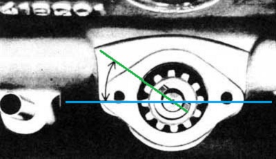
Distributor Drive Gear angular position at TDC1, as shown in the factory manuals,
30 Degrees off the Crankshaft Axis (10 O'clock position).
This is the target condition, but is not the only place one may find it!
Volvo Ignition from Scratch
12/01 R. Kwas, Revisions On-Going [Comments
Added]
Static Timing a B18/20
Dynamic Adjustment of the
Spark Timing or Vacuum Advance OR Vacuum Retard
Centrifugal Advance
Example of Centrifugal Advance Failure
Detailed Centrifugal Advance Servicing.
Centrifugal
Advance Assembly and Component Details
Distributor Lubrication
Vintage Volvo
Ignition system and the Armored Cable.
Troubleshooting the Vintage Volvo
IGNition System.
Ignition
Modifications
Understanding the Failure of a
Diode ORing Cable used with Electronic Ignition Module
Disabling Ignition System
during Service
Troubleshooting the Vintage Volvo IGNition
System
A Word on
Electronic Ignitions
Waveforms of the Kettering
IGNition System
Quick Ignition Troubleshooting
Info
Glenn Ring Dist Rebuild Info
Changing Distributor
Rotational Position
Notes for Repositioning Distributor Drive Gear to the Factory Position
Distributor
Housing and Ignition Wire Variations
Hot wiring a car
Ignition Firing Order
Links to related SW-EM tech articles: Late-Production Ignition Switch (Ign Sw is located on Steering Column, similar to those of the 140)
https://www.sw-em.com/123Ignition_in_a_Volvo_with_Armored_Cable.htm
-----------------
So you've been lucky enough to get a great deal on that vintage Volvo...the way you tell it that is, (not your wife or even maybe your friends)...because there's just a slight problem...the Ignition System is kind of apart...more like an Ignition System do-it-yourself-kit really. This page, in addition to just about any of the available shop manuals, should help you get that Ignition System back together and working, and allow you to keep some, if not all of your hair!
Reassembling a B18/20 Ignition System in Disassembled or Unknown Condition including Static Timing:
For reference: Firing order for B18/20 motors is 1-3-4-2, cylinder closest to radiator is NO.1, a quality beer smells and tastes good even at room temperature and, distributor rotation is counter-clockwise (CCW).
-----------------
Note: The procedures following have been prepared with the utmost care, are however strictly guides, to be used in conjunction with normal cautious shop practice. I cannot be responsible for your specific actions. Work safely!
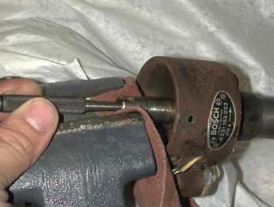
Checking Distributor Installation and Setting Motor to Ignition Point:
1. With ignition OFF and no gear selected. Use a wrench at crankshaft nut holding pulley on front of motor, to turn motor, in normal running direction, to desired timing (16 degrees BTC is a good start), as seen by looking at timing marks on crankpulley and timing cover pointer on front of motor. BOTH valves for NO.1 cylinder should be up and closed (visible by looking into a removed oil filler cap hole). If valves are not up and closed, rotate engine one more rotation in normal running direction, to timing marks, when this condition is achieved (reminder, this is a 4 stroke - Otto cycle motor, where TDC of cylinder No. 1 occurs once for every TWO times the timing marks come around on the pulley). Leave engine at this ignition point for rest of this procedure.
Note: If distributor is not installed, continue with Step No. 2., if distributor is installed proceed to Step 3.
2. Verify angle of drive slot position in distributor drive pinion as approximately 300 degrees when looking from distributor side of engine (see Pic below!). If repositioning is necessary, lift pinion to remove, turn appropriately (as engagement with Cam is a bevel gear), and reinstall pinion to achieve correct position (it will be necessary to turn motor to engage drive pinion with cam, and drive of Dist Dr Gear with Oil Pump Drive below, so Step No.1 must be repeated!). Install distributor, which has been checked over and has had points gap set at .016" (turn rotor to turn shaft until engaging pinion drive slot), then lock distributor holding collar to engine block.
3. Remove distributor cap.
Determine to which plug wire the distributor rotor points when cap is in place. Starting with
this wire, verify and/or correct wiring of firing order as 1-3-4-2. (See
also: Ignition Firing Order)
Distributor Drive Gear angular position at TDC1, as
shown in the factory manuals,
30 Degrees off the
Crankshaft Axis (10 O'clock
position).
This is the target condition, but is not the only place one may find it!

Approximate view when Distributor is installed with Drive Gear in the factory
position. Notice Rotor also points to the 10
O'clock position, Distributor housing can be turned (after loosening Housing
Collar Clamp) so that Rotor also approx. aligns with
circled
Reference Mark on Housing edge.
4. Assemble rest of the distributor and ignition system and proceed to Static Timing.
The above procedure is intended to return the Dist Drive Gear to the factory position...what happens it it is not in this position? It's not the end of the world! See also: Distributor Housing and Ignition Wire Variations below!
-----------------
This procedure is to be performed AFTER: engine has been set to ignition point, distributor drive pinion and distributor have been correctly installed, cylinder No. 1 ignition wire has been determined, all ignition wires have been installed in the correct firing order, setting the points gap to .016", checking for free Centrifugal Advance, smooth return, and lubing CA mechanism with a few drops of engine oil (felt pad located in shaft center under distributor rotor).
1. With all ignition components in place and assembled, set motor to ignition point (see preceding procedure), remove plug wire from Cylinder No1. spark plug, and lay onto valve cover with a gap to cover so that a spark will be visible when it occurs.
2. Turn ignition ON with key.
3. Loosen timing adjustment locking nut on distributor Housing Collar Clamp.
4. Turn distributor housing CCW about 45 degrees to assure points are closed, and it is therefore positioned BEFORE ignition point (point at which lobe on distributor shaft opens ignition points and causes high voltage spark). Note: This procedure can still be used, even if ignition has been upgraded with electronics which eliminate the points, and replaces them with a Hall-effect, or an Optical sensor.
5. With ignition rotor, cap, wires in place, slowly turn housing CW (simulating a normal CCW distributor shaft rotation) until spark occurs at test gap. Repeat steps 4 and 5 as many times as is required to get a feeling for when the spark occurs, and to be able to IMMEDIATELY STOP turning the housing after the spark does occur.
6. Turn ignition power OFF with key, lock timing adjustment by snugging timing adjustment locking nut on distributor collar, restore No. 1 plug wire to No. 1 cylinder, assure ALL IS SAFE and engine is clear to run.
7. Ignition system is now timed and presuming all else is in order (fuel), engine can be started and run. After applying choke, handbrake, placing gearbox in neutral, engine may be started using ignition key and (preferred) Start push button (or better yet, Service Switch under hood!).
8. It may be necessary to reset the idle after timing. This should be done after choke has been disengaged, engine has come to normal operating temperature as indicated by thermostat opening (as can be seen on temperature gauge).
Note: I have used this this Static Timing method for years, and found it to be absolutely fine, and perfectly adequate for the B18/20 engines...after timing in this manner and checking with a timing light (NOT mine - I don't own one!...what for?), I have found that my adjustments, performed according to these procedures, have put the timing within one degree of the 16 degrees specified...can't argue with that!...plus, since minimal tools are required, this procedure can be performed - if necessary - on the side of the road, although the garage or driveway, with a well stocked fridge not too far away is clearly preferred! Cheers!
-----------------
Dynamic Adjustment of the Spark Timing or Vacuum Advance OR Vacuum Retard?
General: In addition to the fixed Ignition Timing setting which we can set statically, as above, when engine is not running, the actual timing of the spark during engine running is further influenced by the Centrifugal Advance, a mechanical system controlled by rotational speed (RPM) of the distributor itself, and also a Vacuum Advance/Retard (if installed, year and model dependent). Both of these systems function by further varying position of the top of distributor (where lobeshaft controls the points), from the bottom of the distributor (mainshaft is driven by the camshaft). In the case of the vacuum system, it is possible to generally verify its operation by disconnecting vacuum tube at distributor, connecting a test vacuum tube, providing some test suction, while watching for movement at movable points plate (any leaking-down or outright failure to operate is a sign of a jammed points plate or damaged diaphragm). Here's a cute little animated graphic which I couldn't help stealing from a very informative automotive site: [http://www.kfz-tech.de]

Vacuum dependent timing adjustment in action. It can be seen that the Vacuum diaphragm
action changes position of the plate on
which Points are mounted CCW, and in the same direction
as the lobeshaft is
turning. Given shaft rotation is also CCW, this would
make point opening occur later,
so it is an animation of a Vacuum Retard configuration.

Vacuum Advance Configuration. Note position change of Vacuum
mechanism,
and that it now rotates Points in the opposite direction and into lobes...so
Points opening would occur earlier.
Distributor shaft rotation,
Points plate rotation.
Vacuum Retard vs. Vacuum Advance? PLACEHOLDER for comparo...bottom line is: Retard is performance-killing and for weenies! I will try to locate and add a link to Phil Singher's excellent explanation which doesn't need anything from me to be added!
Centrifugal Advance In the case of the centrifugal system, it is a bit more subtle...centrifugal weights below the points plate, their rpm dependent force working against Primary and Secondary Springs, vary the relative position of the stacked concentric shafts of the distributor. Clearly, it is not possible to accurately check this action when motor is not running, but by turning an installed rotor, CW about 20 degrees, one can get a pretty good general idea of the state of the CA mechanism. A smooth rising return force action against the springs should be felt, returning to the non-advanced position when released (any step or binding, or non-smooth action is a sign of problems which can cause erratic engine surging while driving). I have seen wear of the centrifugal weight assembly (on a number of different distributors), which resulted in the centrifugal weights not moving smoothly, but this will take another specific section to cover. See: Detailed CA Servicing.
The springs are arranged for a rising return rate action, that is, initially Primary Spring acts against the turning force of its centrifugal weight, and at some predetermined RPM, the Secondary stronger spring, working against its own centrifugal weight, contributes its force. In this manner, the springs set the shape of the advance curve, in some configurations, as shown below on the 099 version, with a distinct "knee". Notice the two slopes of the advance curve here, and finally mechanical stops limit the advance at some maximum (the two advance curves shown are for the acceptable range when testing).

...099 Curves marked up...Note: Data is from the standpoint of
Distributor, so RPM are 1/2 Crankshaft RPMs.
Contribution of force by
Primary
and Secondary
CA springs is shown.
Graph source: Bosch
Link to Distributor details for B20/B30 units including Centrifugal Advance (in Degrees/RPM), and Vacuum (in Degrees/mm HG) values:
http://www.networksvolvoniacs.org/images/9/90/Verteilerkennwerte.pdf
Example of Centrifugal Advance Failure:
From Thread: Damaged JFUR4 distributor https://www.volvoforums.org.uk/showthread.php?t=308455
Symptoms: "The car ran well and felt lively enough but there was obvious pinking [British for what we American rebels call "pinging"!] on acceleration in top gear up-hill. So I did the usual thing and backed-off the advance at the distributor. Things got a bit better, but still some pinking on acceleration up-hill. So I backed-off the timing a bit more, but the pinking is still there."
"...looking at the distributor. I wondered if there might be a problem with the centrifugal advance, and indeed there was. The mechanism is quite free and the light spring is fine. However, the heavy spring had become detached at the outboard end. On closer inspection it looks like the top of the attachment-point has broken off."
With Secondary CA Spring disconnected, I expect the advance curve looked like this, putting his engine into "Ping City" [...and that ain't in china!]:

Cenfrifugal
Advance Curves for 099 B20 Distributor with
Secondary Spring failure curve added
in Red.
The Advance comes up much faster for a given RPM explaining the pinging symptoms
this owner experienced.
Service and Maintenance suggestion:
It's always good practice when doing an oil-change, to pop the Dist Cap off, and "feel" the return action of Cent Adv, by gently turning the Rotor CW. This way, one might get used to the expected "rising rate" spring return force, and the owner of the above car and Dist might have "felt" when the Secondary Spring force was not detectable, clueing him into the cause of the symptoms... ...and while your Dist Cap is off, to pop the Rotor and put a drop or three of the new, clean oil onto the felt "oil reservoir" which lubes the concentric upper lobeshaft.
The info presented here is in addition to distributor tune-up information found in just about any decent shop manual. The intent here is not to copy what they already cover (and every vintage Volvo owner should have at least one as a reference...preferably slightly soiled by oily hands... to show use, but also that a certain amount of respect was showed to the book!), but to augment their basic coverage with more detailed handling of what can occur due to high mileage, or what I call "excessive maintenance", etc.
Indication that there may be a problem with the CA mechanism. Poor Starting. High idle when it was previously fine (but otherwise decent running) is possibly a sign that the CA mechanism may be bound up, and not returning to the non-advanced position. Surging of engine can also result if advance occurs not smoothly but in steps... Incurable and seemingly excessive Pinging (see Example of Centrifugal Advance Failure above!).
Checking the CA mechanism is simple! Remove Dist cap, rotor should be against the CW stop and not be able to be turned further in that direction. If it is possible to turn it CW, it means it's time for a CA mech inspection. On the other hand, it should be possible to turn the rotor in a CCW direction for about 20 degrees, against an increasing return spring force. The movement should be smooth and return fully to the unadvanced position. If distributor is not installed on engine, distributor mainshaft must be held in place before the same checks can be performed.

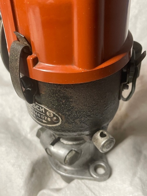
Bosch xxx078 distributor
with Vacuum Retard. The plate on which the once-piece points assembly
mounts is also movable by vacuum, in this manner, vacuum also adjusts the
timing. This distributor has the vacuum diaphragm pulling the plate CCW,
therefore it is arranged for vacuum retard. Some models were set
up as vacuum advance distributors. CA mechanism is
under the points plate.

View of the CA
mechanism of an xxx003 distributor, once points plate has been removed. Note the
Primary
and Secondary
Springs, and that one end of the Secondary Spring has an extended end-loop
(visible on its left), which allows the loop to slide, and importantly, not
contribute any return force until the "knee" in the curve is reached
(more correctly, the knee in the advance curve is a result of the beginning of
force contribution of the Secondary Spring).
To check action, use a small screwdriver placed in the depressions of the
weights. They should freely move through their arc (causing Lobeshaft to
turn with respect to lower shaft), against the return force of
the springs.
Disassembly of dist Carefully remove CA springs. Remove circlip. See following:
|
|
|
After "C" clips retaining CA weights are removed, weights, fibre washers, and height bearing (three arrows) may be removed for inspection and cleaning.

CA
weights can jam up when supporting fibre washers are damaged or worn below minimum
thickness, it is important also to remove, inspect, and clean the (center)
plastic (height) bearing.

Off-center wear is evident
on centrifugal weight. This can occur with worn fibre washer, height
bearing, or bent contact cam on lobeshaft.

Polishing the lobeshaft to perfection! A polished lobeshaft and just a bit
of lube on reassembly makes for a happy, long-lived, points-rubbing-block!
Visible are washer and circlip used for securing lobeshaft.

Polishing the mainshaft to an equal perfection! Note discoloration on
shaft, probably caused by inadequate or overheated, and oxidized lubricant.
A polished, well lubed mainshaft makes for a smooth, repeatable CA curve. The fibre washers
seen here
look to be in very good shape.
Centrifugal Advance Assembly and Component Details:

Heavy Spring is hooked on post with "180" punched in (Orange)*.
Fibre height washer under CA Weight is measured at 0.040" thick (Blue).
Washer and Circlip which secure Lobeshaft onto Mainshaft at (Green).
Clearly evindent again is the extended end-loop of the
Secondary
Spring.
* Since fine tuning of CA Curve is implemented by fine bending of Posts which CA Springs are located on, if CA Springs need to be removed during servicing, they should be returned only to the post "from which they came"! In the case of the Distributor above, Heavy Spring is secured at one end by Post next to "180" label, but since author cannot guarantee this labeling is present on all Distributor models and revisions, marking things at disassembly time (or even taking some reference pictures), to assure they get back together "from which they came", would be the preferred practice!
** Note also that base (punched "002") Centrifugal Weights are located on, has been removed from mainshaft in the picture. This means that rotational registration between the two is lost and would have to be reestablished at reassembly (more witness marks required!). To prevent needing to do this finicky realignment (recommended only to be undertaken by expert level mechanics), author recommends against separating the two for servicing!
Distributor Lubrication: After careful disassembly, inspection and cleaning, reassemble with a film of engine oil...I now use synthetic motor oil for its consistent viscosity over a wide temperature range, and to possibly prevent gumming due to cooking which may have contributed to the jamming of the Snow Weasels CA mechanism. See: A Tune-up out of Guilt, Update II
Reassembly is, as they say, "the reverse of disassembly".
Don't forget a couple of drops into the recess on the top lobeshaft, and to soak and replace the felt, and to fill the little (turn cover) oil reservoir at the outside beltline of the distributor with (normal) engine oil (this lubes the mainshaft in the housing, eventually draining into the sump, and it's not right to mix wine and beer)...better yet, since it wasn't included in many manuals, here is the official exploded distributor lubrication diagram, showing how important, and extensive the recommended distributor lubrication really is. 4,5 and 8 are the really important ones!

Source: intereurope Workshop Manual
162 ISBN 0-85666-066-3
From a Forum posting of mine ( http://www.volvoforums.org.uk/showthread.php?p=2051541#post2051541 ) :
A quick check on Centrifugal Advance is something that can, and should be performed whenever Dist Cap is off (as well as adding a drop or two of oil to felt "reservoir" at top of Lobeshaft under Rotor...remember, the Distributor is strictly a mechanical system, no computer in sight(!), and mechanical systems need to be lubed. See here for all the other places on Distributor which should be lubed: http://www.sw-em.com/Volvo%20Ignitio...or_Lubrication ).

Felt pad reservoir for the important Cent Adv. lubrication,
and underside of Rotor showing registration key and retention spring.
By simply turning Rotor in the Counter(Anti)-Clockwise direction, a smooth,
increasing spring counter-force should be felt, and rotor should return smoothly
when it is released. If there is any non-smoothness, or high resistance to
turning, or non-returning to starting angle is noted, CA has an issue which
needs to be resolved.
Proper CA action is quite important to a good running engine! Ignition Timing
which doesn't advance smoothly can cause engine surging like a bucking bronco,
and timing locked at one place, and which does not advance at all with RPMs,
results in an engine which feels like it's being held back (because it is!) with
all the performance of a road-slug. Lube your CA!
The other important point for lubrication is number 8 on the diagram.
Oil Reservoir Cup (8) for important(!) Bushing Lubrication.
The little Dustcap is shown turned open for filling.
-----------------

The Bosch xxx003 distributor...reassembled with a new tune-up kit, gapped to
.016", checked with an Ohmmeter and ready
for installation in the Snow Weasel, static timing, and another 50k miles of
trouble free service!...nah, I promise to do more regular tune-ups and
maintenance! Rotational (Timing) Clamping Nut highlighted in
Blue.
-------------------------------------------------
Vintage Volvo Ignition system and the Armored Cable
The vintage Volvo IGNition system is a classic, simple, points and coil design. It does feature two notable differences which set it apart from ignition system found on American Vehicles of the era, which a mechanic may be familiar with.
1. No Ballast Resistor. In IGN systems which employ a ballast resistor, the trick of running the coil at part voltage under normal operating condition (with the ballast resistor dropping part of the voltage), while applying full battery voltage during cranking, is employed (by shorting across the resistor with the IGN switch while in the Start Position). This improves the chances of starting by working the coil harder and increasing the spark voltage during starting, while letting the coil work at a less stressful and cooler operating point normally...but apparently designers at Bosch figured this was unnecessary, figuring out a way to reliably start and also eliminate this component and the complexity that switching it into and out of the circuit brings. [There is no Ballast Resistor hidden in the Ign Coil of a vintage Volvo Ign Sys either, contrary to what you might have heard by the armchair experts on Faceplant! The inductive and transformer characteristics of the Ign Coil were instead carefully engineered by Bosch not to require one!]

Vintage Volvo integrated Ignition assembly. Ignition Coil is permanently
connected to Ignition Switch
by way of an Armored Cable which protects the Ign Coil + node, and makes it
completely inaccessible!
2. The Armored Cable and Internal-only Coil + Terminal. It is also not possible to “Hot-Wire” a vintage Volvo! [“Hot Wiring” is defined as bypassing the IGN Switch, and applying battery power with a “Hot Wire”, to the positive terminal of IGN coil] . In vintage Volvos, there is simply no access to this node (see diagram below) to connect this "Hot-Wire", so there is just no way to get the IGN system to function without applying power...only the IGN Switch can apply power, and it requires the key to turn! The connection between IGN Switch and Coil is further protected by the Armored Cable of fame and lore. This is a pretty effective anti-theft measure...if you don't have the Key, you cannot activate the Ignition!...and we vintage Volvo owners like it that way!
Reference: Hot wiring a car
Unfortunately, the Armored Cable also means that since the Coil + terminal is not available/accessible for checking, so these Ign Sys are trickier to troubleshoot for the unfamiliar, and it's easy to get it wrong, so Coils and Ign Switches are not infrequently wrongly declared to be "Bad" and replaced by uninitiated, non-vintage-Volvo mechanics...but proper troubleshooting is still possible!...the following graphic, comparing a typical Points based Ign sys on the left, with the Armored vintage Volvo Ign Sys on the right, shows all the internal secrets and what one needs to know...remember, when Ign is ON, and Points are open, a test-lamp touched to Points node will light OR a Voltmeter will read Ign 12V, and when Points are closed, it Test-Light will go out OR Voltmeter will read 0V! Simple!

On Left, a standard sixties
Kettering IGNition
System with Ballast Resistor one might find in a sixties American car,
and on Right, Volvo’s (Bosch) version
without Ballast Resistor, but with the “Armored Cable”, and
inaccessible + node.
Note that the Ign Coil positive node does not protrude from the Coil housing,
instead exits only at the rear mounting surface!
Also, noted in GREEN, the fact
that Ign Pwr at the Ign Coil can be checked at Points node when Points are open,
since it cannot be checked at Coil + terminal (there is no terminal!).
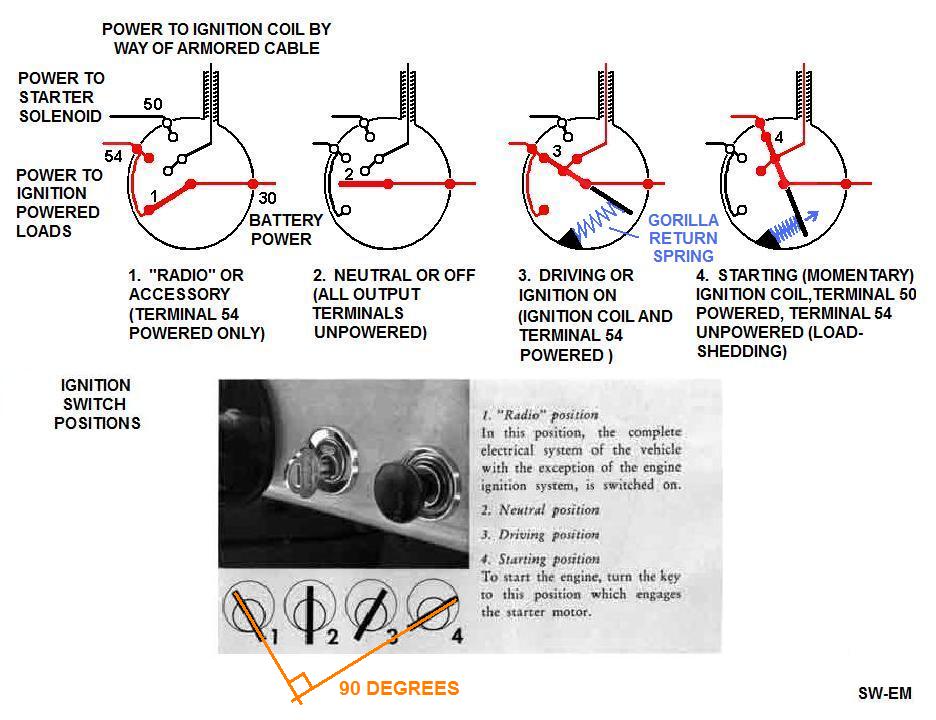
Further details of the internal switching of the IGN Switch can be seen in the diagram.
Position 1. “Radio” or Accessory Position: ONLY the IGN power terminal (54) is powered.
Position 2. “Neutral” or Off Position: No terminals are powered. (This is the only position the key can be removed in.)
Position 3. “Driving” or Ignition On Position: In addition to the IGN power terminal being energized, power is also applied to the coil positive node (not otherwise accessible, see text).
Positon 4. “Starting” or Momentary Start Position: Power is removed from IGN power terminal 54 (to shed additional loads and eliminate the resulting voltage drop during starting attempts), and power is applied to the Starting terminal (50)...power continues to be applied to the coil positive by way of the connection protected within the Armored Cable (see IGN Switch internal diagram). This is a momentary position against the force of a GORILLA RETURN SPRING (see below). Turning the Ign Key against this spring repeatedly is what causes metal fatigue in keys and results in them breaking...this why you can also call this IGN Switch position the “Torsional Key Test Position”, and why you should NEVER have just one key, and might seriously also want to consider installing a Sw-Em Start Switch Kit!
Here, in detail, is
everything one always wanted to know about the workings inside of the Ignition
Switch:
See also: Ignition Switch Key
Breakage Tech Article Note that the
GORILLA
SPRING is shown simplified here for
purposes of clarity.
Ignition Modifications: The internal connections and workings of the vintage Volvo IGN switch must be carefully considered when making modifications like the Sw-Em Start Switch Kit (and rest assured, the author has!), or upgrading to an electronic IGN module to eliminate the mechanical points....because of the disconnection of power to the IGN power terminal (54) during cranking (see inner workings of switch), it is not enough to simply power an electronic IGN module from this terminal...it doesn’t get power during cranking!...so wouldn't work so good! A Power ORing Cable consisting of two (or one) diode(s) connected in a power ORing circuit (power is routed from one OR the other source) must be used.
Power ORing Cable (Two Diodes)

"OR"ing power connection. OC = Other Connection(s).
Power ORing Diode cable (Single Diode) for powering electronic Ignition Modules, (as offered by IPD
for instance).
This is a Single Diode version of the two Diode ORing cable shown above, and serves the same purpose: To supply an uninterrupted power to an Ignition Module. It can work in a single Diode version because this takes into account the fact that no power is present on Term 54 during cranking (with key)...it is disconnected anyway, so diode is really not absolutely necessary on terminal 54 while Key is in Pos 4, and there is really no need to have Ignition Module power flowing through a diode under normal running conditions!

Power ORing Cable employing a single Diode.
Reference information: ORing Circuit Notes
Understanding the Failure of a
Diode ORing Cable used with Electronic Ignition Module:
Recently, a question came up on a 122 retrofitted with an electronic Ignition
Module, plus a (single) Diode Cable, but still with the original Lock Cylinder and Key
doing all the work (no Sw-Em Start Pushbutton - this is significant!). It seems
that owner was having difficulty Starting in Key Pos 4 (actually, he reported it would NEVER
Start in this Key Position, when formerly, it did!), [Owner reports: "The
car will not start when the key is turned to the right and the engine cranks.
It will only start when I release the key and it returns to the on/running spot.
"] ...but the interesting symptom that sometimes it would
Start just as he released the Key to Pos 3. In reviewing these symptoms, it is
actually possible for author to logically explain this action by the fact that
the diode has opened (so no power is available from Terminal 50 while cranking),
but becomes available from Terminal 54 the moment Key is released, enabling Electronic
Ignition Module, which produces Sparks, and allows Engine to fire...if you're
lucky!
Summarizing symptoms if Diode fails. Engine NEVER Starts while cranking with key (because Ignition Module is unpowered since Diode path is open), but seems to fire up and maybe even Start when Key is released from Pos 4 to Pos 3 (module then gets powered, so Ignition Sparks now occur while engine is spinning down from inertia)...if State of Tune, and State of Battery Charge is good (fast cranking), a Start may occur (Owner is Lucky!).
Reason why diode opened in the first place can only be conjectured...it might have been due to any number of reasons, including a Load-Dump Surge (Link: Supporting information: Load Dump Surge ), but most likely, the diode taking a lethal shot from the Reverse Voltage Spike from Starter Solenoid...this is a big inductive Load which will generate a major reverse Spike (shown in Ignition System voltage graph, in Red below) when Ign Switch is released from Pos 4 and contact opens, very much like Ignition Coil Primary, that the Blocking Diode must be sized with a generous Peak Inverse Voltage (PIV) rating to survive this significant Spike!
I am still awaiting failed diode information, so that I can see what the PIV rating is for the component, but request anyone with a Failed Cable exhibiting these symptoms to contact the author...I would like to do a post-mortem on one! [See Update below.]
Below a bit more info on this Spike, and a Concept to add a Clamping Diode (same component, different electrical location and function, shown in Green) to suppress this Spike.

Explanation of how ORing Diode is damaged, and a concept for adding a Clamping
or Flyback Diode (or about a half dozen other names), preventing this.
See also:
https://en.wikipedia.org/wiki/Flyback_diode
Bottom line again is to install the Key saving Sw-Em Pushbutton Start Switch (highly recommended anyway!)...then all tricks and complicated provisions necessary for providing uninterrupted power to the Ignition Module become moot, simply fall away and become totally UNNECESSARY! Easy! See also Tech Article: 123Ignition in a Volvo with Armored Cable.htm
[Update: Diode was found to be a 1N4006, with a PIV rating of 800V, and it was confirmed failed OPEN. Without measuring the actual reverse Spike, to see what the diode is subjected to, I expect this is an adequate PIV rating which I doubt was exceeded by the Spike, so the diode failure was a random occurrence.

Open 1N4006 from power ORing cable.
After removal of the failed diode and associated wiring, and installation of the (clearly super-groovy) Sw-Em Pushbutton Start Switch, all is once again well, with the side-benefit that the key is now not subjected to high torques while being turned against the GORILLA SPRING!]
[Interesting Related Point: In speaking with an "old-timer" who worked on American cars back in the day, the above symptom of not starting in the cranking position, but upon releasing the ign key to the run position, is actually the same as would occur when the "Ballast Resistor" or associated connections had developed a connection problem!]
---------------------------------------------------------------------------------
A Word on Electronic Ignitions:
My e-mail answer a question on, and my take on electronic ign conversions:
"...as far as being reliable...if that is your goal and target, NOTHING beats a points ignition, when properly set up initially, and then (only occasionally) maintained [See ancient SW-EM Tech Article: A Tune-up out of Guilt or One Set of Points Outlasts the Clintons. ]. I have no electronic ign in any of my cars, (although being an electronics engineer with full knowledge of their advantages, but also being aware of cost-reduction of consumer products, and what that does to their reliability!).
...I also understand some some people like the maintenance-free nature of electronics...then again, increasing the complexity of a system inherently decreases the reliability, (we're not talking high rel mil avionics here!). [...where ultra-conservative, redundant design, first quality and even pre-screened, selected components as well as burn-in reliability testing are employed to make control systems very hi-rel!] and I have heard of the Pertronics failing out of the blue...and when they do, you are stranded...NO THANKS for me!...ask around on the forums for the experience of others, and you will get them from both ends of the spectrum...in the end, what you prefer is your call!"
-----------------------------------------------
142GUY'S Excellent Explanation of Reduced Spark Energy with Electronic Ignition Modules:
"I first became aware of the Pertronics module voltage drop issue when it was raised in my 142 project thread on Swedespeed by another forum member some time around 2014 - 2016. There was a rather extended discussion about the voltage drop across the module which included some estimates of the reduced spark energy. I know that I was initially surprised by the claimed voltage drop across the module and actually had to go out and confirm the voltage drop by measurement. For me, it all became academic when I eliminated my distributor and installed COPS controlled by the Megasquirt controller.
With reference to the most recent time this came up on the Volvo UK forum, I remember there was one member who questioned the results. I think there were some references to the rise time and decay on the high voltage waveform. As I recall there was also some disagreement over the function of the condenser across the points. At the time, I thought it would be interesting to set up a mechanical switched (points) versus electronically switched coil comparison and measure the spark and condenser voltage and duration and currents. I was going to use a relay to do controlled switching of the coil primary and I have a left over Bosch BIP373 (a dedicated 3 stage darlington coil driver) to use for electronic switching. To measure the spark voltages with my scope and the decay voltages across the capacitor / points I had to build resistive voltage divider networks and I actually ordered the high voltage resistors and suitable hardware from Digikey to do this. Being a dummy, I forgot to order a suitable 600 v capacitor so I sort of lost the initiative and then the weather turned nice and I found a whole bunch of other things to do outside. Perhaps this fall when the weather turns cold or if we get some bad weather this summer I might take a day or two to set up the hardware for test.
I had planned on using a small ignition coil I have from an older motorcycle for the test. New ignition coils have become rather expensive. However, I do plan on a scrounge mission to our local pick and pull looking for a suitable evap cannister replacement for my 140 and maybe I will see if I can find a conventional ignition coil. The pick and pull doesn't have many cars that are older than 20 years so just about all of them have COPS.
For your interest, I have attached the datasheet from the BIP373 coil driver. It does show Vce saturated values up to 2.3 volts at collector currents of 8 amps.
"
------------------------------------------------------------------------------
Troubleshooting the Vintage Volvo IGNition System:
The manner in which the high voltage is generated in a Kettering (conventional) spark IGN system takes advantage of some special rules of electronics and inductors. What is important to remember is that the spark occurs due to the magnetic discharge (of coil primary) occurring at the moment of points opening, but that doesn't take away from the importance of what is happening during the time the points are closed...namely to complete the primary circuit and allow current to flow from the power source and charge the coil in the first place!. Both points closed and opening are critical…if either doesn't happen, no spark will result…period!
The IGN switch / Armored cable/ IGN Coil Assembly of fame and lore is a wonderful thing...it makes stealing so equipped vehicles difficult (Good!), because the Coil primary (+) connection just isn't available for "hot wiring" by a thief (see graphic above, and link to realistic video about "Hot-Wiring" a car below )...it also makes troubleshooting IGN system failures by the rightful owner or his duly appointed agent, by measuring voltage on that point a bit more tricky for the same reason…but this should not be a problem for the owner who has the IGN key and understands what is happening, and that is what these notes are intended to help with!
Understanding and Troubleshooting the IGN System:
I am now leary of applying a voltmeter to parts of the IGN system because of the high voltages present...I have personally destroyed an expensive Fluke DVM with a bolt of lightning in this manner during power up tests...and not even of the Hi-Voltage secondary circuit...and this is to say nothing of less expensive meters which are likely to have even less protection and tolerance for surge insults built-in! The spike which occurs at points opening apparently had enough voltage and energy to kill the meter in a millisecond. To spare others the agony, I therefore instead recommend the use of a test light (essentially a low power 12V light bulb with a couple of leads on it.. connected across to points in question, it will light to indicate voltage is present). A DVM can certainly be used without fear during a IGN OFF, unpowered condition, for continuity or resistance checks. Besides, initial checks without a meter can often be informative enough to narrow in on the root cause before one even needs to break out the fancy measuring equipment.
If no spark occurs at the spark plug wires when the points open, several things could be wrong. Among them, (listed somewhat in order of occurrence as I have experienced)...
1. Shorted Points. The connection to chassis may not be opening to break primary current...sure, the points themselves may be physically opening by action of the Lobeshaft, but it is crucial that there be no inadvertent connections (shorts) to chassis on this node, and there is a place where this can indeed occur! If the distributor through-bolt (also Pointsbolt") and its stack of hardware has become uncentered, or the (by now, ancient) piece of insulating paper between points-spring and dist housing has become dislodged or deteriorated and is not insulating that critical connection from touching the chassis, the electrical connection to chassis is not opening and your IGN system is dead in the water! [Troubleshooting Note: With this condition, a test light across point node and chassis will NOT light when points are physically open, to indicate voltage across points, because they are NOT ELECTRICALLY OPEN...remember, no voltage can occur across closed/shorted points! Correct and expected action is that when points are open (IGN ON, of course), voltage is present across points and test lamp lights].

Pointsbolt Stack with minuscule shoulder of Shoulder-washer and
insulated Centering Ferrule added at
RED
to assure Bolt stays centered in the through-hole.

Super-Groovy Centering Ferrule (Green) assures Points-bolt
cannot contact Distributor Housing.
The ferrule is snug on the Bolt, and there's plenty of room to ID of hole, so a
length of insulation harvested from a wire, and stuffed in there, or even a tiny
O-Ring, would do it too...critical goal is to keep the bolt away from the Housing,
with an insulator, and maybe even centered with the SGCF!
2. High Voltage Leakage: If no spark is seen at the spark plugs, it doesn’t by a long shot mean that the high voltage is not being generated...it's just that high voltage has a definite preference for jumping to the nearest and easiest chassis point available to it...and under normal conditions and as designed this is at the spark plugs, but if under abnormal conditions, this happens to be elsewhere from the spark plugs, you can be quite certain that it will jump there, and the High Voltage will never make it to the plugs. That is why it's always advisable to check for the High Voltage at the coil output wire first (by doing this, you separate the High Voltage generation part of the system, from the distribution part of the system for troubleshooting…divide and conquer is often an effective way of locating electrical problems!). Proceed by disconnecting the middle (Input) High Voltage wire from Dist cap and laying it on a convenient chassis location like the valve cover, with a slight spark-gap at which the output spark can be observed. Have an assistant turn ON the IGNition and then activate the starter to turn over the engine (or do it yourself by turning ON IGN with key and activating Starter with a Remote Starter or even more convenient, by activating your engine-compartment SwEm Service Switch). Having checked that the Points and Coil are making the high voltage, one can now move on to the distribution process for which this assembly is named...divide and conquer IGN problems!
3. Distribution Problem: Once it has been determined that High Voltage is being indeed generated, the routing or “distribution” needs to be checked. As the High Voltage comes in on the center connector of the Cap, it gets connected by a spring loaded carbon brush, to the Rotor. As this rotor turns, it lines up with contacts of the circle of contacts of wires running off to individual sparkplugs. (Ref: https://www.sw-em.com/Check_Your_Distributor_Cap_Brush.htm ) One thing that may come as somewhat of a surprise to casual mechanics is that in addition to the High Voltage jumping the gap at the sparkplug (well known!), it also must jump the small gap between Rotor and fixed contact for the wire running off to each cylinder's sparkplug (not so well known!)...no big deal except that the carbon dust from that Rotor contact brush (combined with some early morning condensed moisture) may someday, if not periodically cleaned, present an easier path to chassis for that High Voltage...then it becomes a big deal! Dirt, especially conductive dirt (carbon dust!), is the enemy of a properly working High Voltage system!
X. The very last thing (on my personal list), would be a failure of the IGN switch or coil...while not impossible, I just wonder how many IGN switch / armored cable/ IGN coil assemblies have been condemned because of the troubleshooter's inability to deal with them to correctly locate and remedy the true problem...furthermore, I offer a hot-fudge sundae and to cover shipping (within continental US only!) to anyone who will send me a failed assembly for a post(alleged)mortem inspection! [No-one has taken me up on challenge yet!]
See also: Quick Ignition Troubleshooting Info
Excerpt of a posting to Swedespeed thread: Testing an Ignition Coil: http://forums.swedespeed.com/showthread.php?545666-Testing-an-ignition-coil
....First, perform Static Test with Ohm
Meter function of your DVM (this may be done on a bench with Ign Sw/Arm Cab/Ign
Coil Assy stand-alone, or while installed in vehicle, if Battery is first
disconnected)...and note...since there is no (direct) access to Ignition Power
terminal of Ign Coil to check Primary continuity, simply place Ign Key in Pos 3
and use term 54 as one end of the Primary...(IIRC, Primary R should be around
3-5 Ohms)...
Power-up Test (this can also be done on bench or while Assy is installed
in vehicle) : Connect as normally (don't forget... chassis is the return path to
Bat negative), apply Ign Pwr, then make and break Points, either with a
conductive tool like a screwdriver across the points, or a simulated "Points
connection" on the bench. Watch for spark...
Edit: Having lunched an expensive Fluke DVM doing this, I recommend against
using a DVM to check any voltages during the Power-up Test (even just the "low
primary V" across Points, which has a serious spike on it at T2)! Getting the
spark at the test Spark Plug every time you open the Points connection will show
it's working as expected! If you don't get a spark, Points may be physically
opening, but not electrically because Through-Bolt at Dist housing (or something
connected to it) is shorting to Dist Housing. ...to check for this (with IGN
OFF!), check from Through-Bolt to chassis with Ohm Meter, when Points are
"open"...there should be no continuity!...
-----------
Disabling Ignition System during Service:
This following is the preferred and safe method of "disabling" the Ign Sys, and should be used ANY TIME we want to turn over the engine with Starter (using a "Remote Starter Switch"), with Ign powered, so that all vehicle functions are powered as normal, but we do not want the engine to start (like priming the Oil System, performing Compression Test, etc).
At certain times, the Ign Sys may need to be "disabled",
meaning we don't want any sparks in the combustion chamber to possibly start the
engine. Simply pulling the center wire from the Ign Coil is not the
best way to do this! If Ignition is ON (in other words, Primary of Ign
Coil is being powered), and Points are still connected and providing the open
and closing function as engine turns, the Ign Coil will still be generating High
Voltage on the secondary, and this Voltage WILL seek a path to chassis, EACH
time it occurs. This can stress the insulation of the Ign Coil in the
process possibly damaging the insulation of the Coil! For this reason, it
is much better to pull the High Tension wire from the Distributor center
connector and lay this somewhere on chassis, where the spark is allowed to
harmlessly jump to chassis, thereby not stressing the Coil. The Ign Coil is
thereby allowed to operate normally and generate Hi V, and this Hi V is safely
given a non-damaging path to chassis. All is good...and safe!
----------
Waveforms of the Kettering IGNition System (See: Who is Kettering?) :
I have found some representative Waveforms on Picotech's site!
Review: When points are closed during operation, IGN coil current flows in the primary winding, building up current (relatively slowly due to primary inductance), thereby storing electrical charge magnetically (see: Primary IGNition Current). When (and exactly when!) points open, this current path is broken, the resulting reverse inductive spike, caused by the very rapid discharge of the primary circuit inductance, in addition to a voltage step-up transformation to the secondary winding, results in a very high voltage spark being generated at the secondary winding (see: Primary IGNnition System Primary and Secondary Voltage and Waveforms.). Both conditions are absolutely necessary for correct function of the IGN system. Points must cycle in order for the IGN system to charge and discharge. Any failure condition which interferes with either of the two conditions will prevent the system from generating the desired high voltage.

Primary IGNition Current. Kettering Ignition System Primary voltage and current
waveforms.
Timing: X= Points close, Voltage across points drops to zero, secondary
current begins rising.
O= Points open, voltage across points spikes up, secondary current drops to
zero.
Graphic Source: Shown

Primary IGNition System Primary and Secondary Voltage and Waveforms.
Timing: O= Points open, voltage across points spikes up, secondary voltage
spikes way up!
Graphic Source: Shown (marked-up)
In updated IGN systems which are triggered by magnetic or optical sensors, a non-contact sensor provides the timing function, and a solid state electronic switch provides the high current controlling function of points, but the circuit action is essentially the same. Note that in the original system and the electronically upgraded systems, the spark only occurs once...and ignition of the mixture therefore only has one chance to ignite...wouldn't it be nice to give it another or multiple chances... In a further advancement of IGN systems, Multiple Spark or Capacitive Discharge Systems (MSD/MCD) give multiple opportunities for ignition to occur...less misfires...more power result.
Multiple Sparks during starting attempts is also the basis of the “Wifes Startomat”
PLACEHOLDER FOR MULTIPLE DISCHARGE SYSTEM STUFF
------------------------------
Quick Ignition Troubleshooting Info
From thread: http://www.volvoforums.org.uk/showthread.php?p=2203057#post2203057
My response and troubleshooting info to a non-functional Ignition Sys:
Note: My following comments apply to an
unmodified Points based Ignition System for vintage Volvos fitted with the Ign
Sw/Armored Cable/Ign Coil Assembly.
Ignition Coil is supplied by Ignition Switch, and since this node is internal to
the Assy (only!, and not externally accessible!), presence of Ignition
Coil power cannot be checked directly...it can however be verified
indirectly (statically) with a voltmeter, by checking the Points to Ign Coil
node for 12V, while Ignition Switch is ON, and Points are open (remove
Distributor Cap to allow visual check of Points condition!).
Alternately, and next, a more comprehensive functional check of Ignition Coil
can be performed (also with Points open), by turning Ign Sw ON, then shorting
and unshorting across Points repetitively (with for instance a screwdriver),
while watching for a Hi-V spark from Ign Coil (output wire from center terminal
of Ign Coil removed from Dist Cap and placed near Chassis to make a spark-gap).
If Hi-V occurs every time connection is unshorted, Ign Coil function is
fine...Ignition System should be reassembled normally, except, one Sparkplug
Wire disconnected at Sparkplug and again, placed near Chassis with a spark-gap,
Sparks should be evident, with Ign Sw ON, and Starter activated. Ignition
Function thusly (dynamically) checked, Ign Sys can be fully restored to normal
configuration, and Starting attempts can be made.
------------------------------
Additional Info:
Who is Kettering? Answer: Apparently a pretty sharp fellow from 1910! See: https://en.wikipedia.org/wiki/Delco_ignition_system
------------------------------
Good detailed Bosch Distributor Rebuild info: http://www.glenn-ring.com/010/index2.html A Bosch PN ...010 Distributor (as used in Volkswagens, but a kissing cousin to the Volvo units) is refurbished. The observant reader will notice some differences at the Centrifugal Advance Mechanism, but the info is quite applicable to the Volvo distributor.
Use the information on that page in reference, or have your Bosch Distributor expertly rebuilt and checked by Mr. Ring. No, he is not my brother-in-law, but I have communicated with him, and it is clear that he has lots of experience, and knows what he is doing, so I include his info here: http://www.glenn-ring.com/ . If the reader chooses to use his services, please contact me with results feedback.
Mr. Ring checks his work on a Sun Distributor Dyne...does the Distributor mounted on there look familiar? If you ask him nicely, he can probably supply you with the Centrifugal Advance Curve from your unit...manually written down...I'm quite certain that machine doesn't have USB data logging output, (although one could be added)...!.

Sun Distributor Dyne with a Bosch unit mounted for tests.
-------------------------------------------------------------
Changing Distributor Rotational Position without changing Ignition Timing, because Distributor is fouling against the engine block, not allowing further rotation and adjustment.
Occasionally, the question comes up from a casual mechanic, of what to do when the Distributor Rotational Position is such that the Vacuum Diaphragm (or in the thread cited below, Oil Cup) contacts the engine block, preventing further rotation for the purpose of Ignition Timing adjustments. What is needed here is to be able to turn the Dist Housing without loosing the Timing (or Firing Order, obviously) of the Ignition Wires coming from the Dist Cap.
From Thread "Distributor Adjustment Knob": http://www.volvoforums.org.uk/showthread.php?t=266863 : [Additional info and comments not part of the original posting.]
edworcs;
Kay has answered the question, what it does...to augment, there are many places
where a Distributor is supposed to be lubricated (4, 5 and 8 are the really
important ones which should be touched up at every Ignition tune-up):
Source:
http://www.sw-em.com/dist_lurication.jpg
Further...while I understand the Distributor shown is not yours, it is clear
that this Dist has Vacuum Diaphragm, I expect yours does not, because if
it did, VD would surely hit hit the engine block before Oiler Cup(8), preventing
further adjustment. Please confirm this...and after confirming, you may use the
following procedure to address your issue, the Root Cause of which is Either:
Engagement of Distributor Drive Gear with Cam has been changed from standard and
nominal position , as shown following, to something else (this is not a
problem per se, as proven by the fact that engine runs normally, other than this
minor issue it causes.)
OR, Ignition Wire location has been changed by one or more stations, resulting
in this abnormal position of Dist Housing.
Explanation: Since I am not aware of the level of your abilities and experience,
and since you are asking, and not familiar with this and how to sort it, I have
to assume a non-expert level (NO insult intended here!), I will keep my
explanation and recommendations as basic and highly detailed as possible and
geared to an inexperienced mechanic. (Unfortunately, this will make it more long
and wordy, but that is the best way to help you to understand the steps, thereby
assuring success!) While there are multiple ways to sort this, I have written
the following procedure, and with the greatest care(!) to be the simplest:
1. With Battery disconnected, and Ignition OFF, use Fanbelt or wrench at
Crankpulley Bolt, to rotate Crankshaft (in the normal direction of rotation) to
a desired starting Timing point on Cyl 1 (16 Deg BTDC is good).
[Observe at Timing marks on Crankshaft
Pulley and Timing Cover pointer!] Since Timing marks come around twice
per single Dist rotation, remove Dist Cap when you believe you are at 16 Deg
BTDC No1, and confirm Rotor is pointing toward station on Cap which has Ign Wire
to Cyl 1. [You must confirm Rotor is pointing to Cyl 1 before proceeding...if
Rotor points 180 Deg away (to Cyl 4), continue rotating Crankshaft until Timing
Marks come around the next time.]
2. Note Clock position of Cyl 1 Ign Wire on Dist Cap, and note that Rotor in
Dist Housing is also pointing to this Cyl 1 direction.
3. Loosen Timing Locking Nut on Dist Mount Clamp at base of Dist to allow
turning Dist Housing.
4. (Everything up to now has been explanation and preliminary, but: Here's
the Beef!) Rotate Dist Housing approximately 90 Deg Counter-ClockWise (or as
you might say in England: Anti-Clockwise). This will rotate the Housing and
Oiler (or VD if present) which is fouling on the engine block, away and clear.
5. At Dist Cap, relocate all four Ignition wires, one station (90 Deg) ClockWise.
Starting with Ign Wire for Cyl 1, and one at a time (think musical chairs...
four wires, four stations, ClockWise!) Reference info: Rotor rotation is CCW and
Ignition Firing Order is 1,3,4,2.
6. When all wires are back on Dist Cap one station CW from their previous
location, replace Cap on Dist Housing and lock into place using 2 Latch Clips.
Verify correct Firing order of Ign Wires running to Spark Plugs.
7. Reconnect Battery, Turn Ign ON at Ign Key, and perform Static Timing (Remove
Ign wire 1 from Spark Plug, lay on Valve Cover to allow seeing Spark when it
occurs, then turning Dist Housing to simulate Rotor Shaft turning (CCW)...first,
a few degrees CCW, then slowly CW until an Ign Spark occurs. Repeat this back and
forth action a number of times or as many times as necessary, until you get a
feeling for the angle at which spark occurs, then STOP turning precisely after
spark occurs, rotating no further. Static Timing is now complete!
8. Reconnect Ign Wire to Spark Plug 1. After assuring engine is clear to run.
Start engine. Timing should now be fairly close to 16 Deg BTDC, which may be
verified with a timing Strobe. If you checked Timing before with Strobe before
and know what it was, you can adjust it in the normal manner (by turning Dist
Housing and observing change at Timing marks with Strobe) to what you might want
it to be (that was the original issue!), now that Dist Housing is clear and not
fouling with engine block..
9. When Timing fine adjustments are complete, tighten Timing locking Nut on Dist
Mount Clamp at base of Dist.
Wishing you success. Please post any questions if uncertain.
Good Hunting!
[Note to experienced Volvo mechanics: I invite peer review on this procedure to
assure I have not missed anything. I have intentionally not written procedure to return Dist
Drive Gear to its normal nominal position, preferring to keep this inexperienced
mechanic's actions on topside of Dist and somewhat simpler and less
intimidating.]
Additional (for experienced level mechanics!): The alternate method for changing rotational position of Dist would involve removing the Dist after Crankshaft has been turned to the No 1. 16 Deg BTDC position (Step 1. above), to check Dist Drive Gear position based on engagement with gearing on Cam, and changing its location back to the standard 10 o'clock position as shown in picture above, then proceeding with Static Timing. I have intentionally not included this method because the procedure as presented above is less complicated (and less intimidating for a casual mechanic) than having to pull the Dist Drive Gear, relocating it, and reengaging it with the Oil Pump Shaft.
Notes for Repositioning Distributor Drive Gear to the Factory Position:
PLACEHOLDER
-----------------------------------------
Distributor
Housing and Ignition Wire Variations:
The following Diagram is intended to show various conditions which one might
encounter, and the effects and options.
Condition 1 is the common arrangement as setup by the factory.
[When engine is at ignition point for Cyl 1, Distributor Rotor points to
approximately the 10O'Clock position.]
Condition 2 occurs when Distributor Drive Gear has been installed into
Camshaft at some other rotational position that what is shown in
pic above (bearing in
mind that it is a bevel gear and shown is the final position after engaging the
Oil Pump drive...this is visible only after removing Distributor), but Ign Wires and Housing position have been
relocated to compensate. As long as Ign Wires for Cylinders run to their
respective correct locations, everything works fine!
Condition 3 sometimes, (depending on the axial position Distributor Drive
Gear has been installed), when turning Housing to adjust Timing, Vacuum
Actuator may foul on Engine Block...something needs to be done...!
Solution follows:
Condition 4 Distributor Housing has been turned 90Deg CCW to clear
Engine Block AND Ign Wires relocated 90Deg CW to compensate (...a Sum Effect of ZERO!). Note Ign Wires still run to their respective Cylinders, and Dist
Housing may now be adjusted without interference...ALL IS WELL!
The point of this is to recognize that Rotor can wind up pointing in just about any direction, based on where Drive Gear might be meshing with Cam at last reassembly, and Housing does have a preferential position range to allow turning for the purpose of adjusting Timing. This means that Ign Wires may wind up just about anywhere...but as long as they run off to their respective Cylinders, based on starting at Rotor location when Crankshaft is at TDC1, and Firing Order, its not a problem whatsoever!

-----------------------------------------
Hot-wiring a car...great information
for owners/thieves of cars other than vintage Volvos!

...notice he walks by the (Hot-Wire-Proof!) Volvo...!

Notice the Spark Coil has TWO low Voltage terminals, so this is clearly not a Bosch
coil installed in a vintage Volvo!
-----------------------------------------
1800S owning Ole Gern, presents a novel and highly entertaining way of confirming the firing order, in this creative video shown with his kind permission:
Warning of Computer Caution: Be certain you haven't just taken a sip of a beverage before viewing...there is a chance of expelling it out your nose at high speed, and all over your keyboard!!!
-----------------------------------------
External material sources are attributed. Otherwise, this article is Copyright © 2001-2024. Ronald Kwas. The terms Volvo, Bosch, and IPD are used for reference only. I have no affiliation with any of these companies other than to try to keep their products working for me, help other enthusiasts do the same, and also present my highly opinionated results of the use of their products here. The information presented comes from my own experience and carefully considered opinion, and can be used (or not!), or ridiculed and laughed at around the Water-cooler (or worshipped!), at the readers discretion. As with any recipe, your results may vary, and you are, and will always be, in charge of your own knuckles and future!
You are welcome to use the information here in good health, and for your own non-commercial purposes, but if you reprint or otherwise republish this article, you must give credit to the author or link back to the SwEm site as the source. If you don’t, you’re just a lazy, scum sucking plagiarist, and the Boston Globe wants you! As always, if you can supply corrections, or additional objective information or experience, I will always consider it, and consider working it into the next revision of this article...along with likely the odd metaphor and probably wise-a** comment.