

Note that the Wattage of these is similar to the original...
...therefore no increase in current, and no need for any electrical "upgrades"!
Lighting Notes, including
Upgrades
07/03 R.Kwas, updates: on-going
(comments added)
----------------------------------------
Relay Controlled Headlights
Adding Driving or
Fog Lights
Suggested Fog Light wiring,
Driving Lights
Reference Information
Sealed Beam
Headlights Information
H3-Dimensional Specifications
----------------------------------------
Headlights: Original lighting on vintage Volvos was adequate for the era, but with advances in lighting technology, including (finally!) the legalization in the US, of non-sealed-beam units, Volvo original equipment lighting can simply and painlessly be significantly improved with "Plug-and-Play" replacements, which draw no more current than those originally fitted. These upgrades can yield a lighting improvement even before any charging system upgrades or wiring are undertaken...of course, clean, tight, connections along the entire current path are very important. Use anti-corrosive electrical paste on connections!
Painless Upgrade (least expensive!)1. Halogen upgrades to standard 7 inch seal beam elements. (Reference PN H6024) The G-E units shown here are just a reference example...Sylvania and Wagner, and likely others as well produce these:
Note that the Wattage of these is similar to the original...
...therefore no increase in current, and no need for any electrical "upgrades"!
Reference: Sealed Beam Headlights Information
Painless Upgrade (a bit more expensive!)2. Separate reflector and H4 lamp elements.
Examples shown: Hella/Cibie. Again, if wattage ratings of the elements are similar to the originals, no wiring changes are necessary!


These Hella units outfitted with Hella or Cibie H4 elements
would also work well!
Note also: I have seen halogen options available in 6V for owners which want to keep the electrical system original, but would still appreciate an improvement in lighting! Link to Comments on 6V Electrical Systems
Other Lighting: (LED replacements for Brake and directional indicators.) Brake Light Upgrades
Upgrading Headlights to be controlled by Relays: My carefully considered opinion of this modern practice differs from many, who are influenced by the common practice today, justified by decorative low current, illuminated switches fitted on today's cars. It's just not necessary, given the beefy, reliable switches and associated wiring which were fitted on our vintage cars! [See link below!] Wire does not go bad. ["Biodegradable" harnesses of the '80s 240s notwithstanding!] Connections on the other hand do! If you are experiencing dim/yellow headlights, check your system voltage and also voltage at the Lights, and if necessary, locate and minimize any significant voltage drop...it will likely be at a connection/crimp or connector, but this is NO justification for tearing the entire system apart and installing headlight control relays...it just ain't!
Before you go and install relays to control your headlights, in order to get good voltage to them, please check the easy things first! (See for instance: Voltage Drop in Headlights Power in Hex Connector). Make this connection right, eliminate the voltage drop, and you just may just be able forget about installing relays to bring the lights back up to full output!

...or a pseudo technical mumbo-jumbo justification for using piss-wimpy switches
and relays to control headlights! This
does not apply to vintage vehicles, particularly our vintage Volvos,
whose Light Switch was a solid, well constructed switch EASILY capable of
reliably switching the full Headlight current!! I recently took one of the
122 Switches apart for evaluation, and was really impressed how well
constructed it was. Watch this space!
[Update - Link to:
Amazon Lightswitch Review and Notes
]
This argument is absolutely INVALID when using suitable switches and wiring, as present in vintage cars! This is common practice when designing new cars, in order to (possibly) save on wiring, but more likely in order to be able to use decorative (but electrically wimpy) switches and associated relay control wiring. The only arguable justification on older vehicles might be to "go easy" on vintage switches and wiring, but if headlight Wattage (therefore current) is not increased, vintage switches and wiring will not be subjected to additional/increased current beyond what they were designed for and perfectly capable of handling.
----------------------------------------
You may consider upgrading your lighting system to include some additional lighting once you have upgraded your electrical system with more generating/charging system power (and not before!).
Considerations in wiring up these modifications. It is well known and accepted that wiring up additional lighting requires using a relay to control the high currents. These are typically even included in a kit. The reason is: Resistance Heating of the electrical contacts of the OE light switch if we were to just add the new load to the OE light switch. This is straightforward. What may be a bit more subtle is where the lights themselves are supplied from....because the entire current path must be considered!...so that if we supply the lights with Ignition Power from the OE fuseblock, we will still be running the significant additional current through the IGN switch. This should also be avoided!
Note that in the original wiring, the Headlights are not an IGNition powered load...it might seem that this is for the obvious reason that we may want to turn ON the lights any time, even when the engine and generating/charging system are not running (even though this would discharge a battery in due time, in fact headlights left ON and forgotten after parking are the most common cause of a flat battery. See: Headlights-On Reminder), but also for a slightly less obvious reason that if headlights were an IGNition powered load, all of the lighting current would be routed through the IGN switch, so a beefier (more expensive) switch would have to have initially been installed. It is for this reason that similarly, we do not want to power any upgrade lighting with IGN power, so that we also do not subject the (vintage) IGN switch to this current unnecessarily.
Here is a good solution to adding Ignition powered Loads: Add an Ignition Slave Relay!
Referring to the following excerpt from the 123GT wiring diagram (http://www.intelab.com/swem/123GT-Wiring-Diagram.jpg ), we see that the additional lighting circuits are in fact powered directly off the alternator output by way of a secondary fuseblock. Also, (only) the relay coils of the addition lighting circuits are powered by the circuits standard in the base model 122. The observant viewer will also notice, that the relays are of the separate coil / working contact type (Four Terminal Relays!) unlike the typical three-terminal relays where the coil power is tapped off the load power see below.
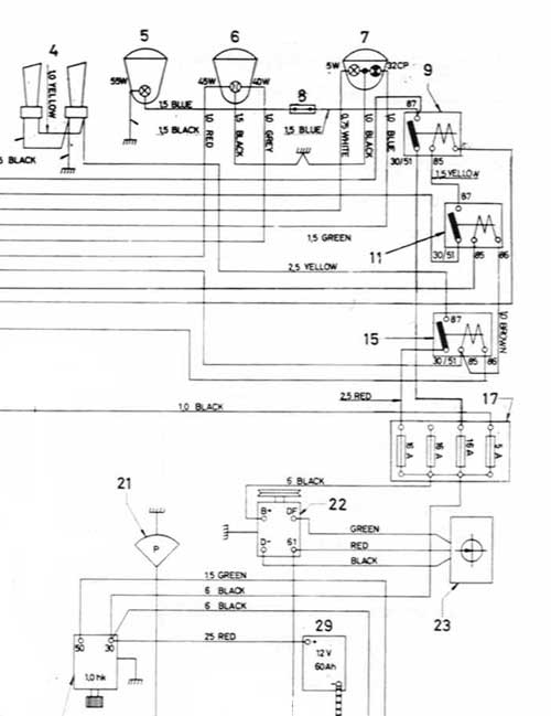
Part of 123GT wiring diagram showing relays and wiring for
addition lighting.
Bottom Line: We do want a control relay to do the heavy duty switching work of additional lighting, and after carefully considering the entire current path and with clever wiring, it will, however none of the vintage electrical components will be subjected to new currents in excess of their original designs.
----------------------------------------------------
Related link: http://www.volvoforums.org.uk/showthread.php?t=112169

Here is the general suggested wiring for adding fog lights, front and rear to a
vehicle.
Power should be taken by way of a new fuse of suitable rating, from Battery plus post (or Starter Post)...in this way you wouldn't have the Automatic-Off function you would have if you took power from Ignition power Fuse2 for instance, but you also wouldn't be subjecting the vintage electrical components to any significant additional currents...this is an important consideration and much preferred from a reliability of existing components stand point! [Better yet, is to supply the "Fused Power" for the above circuit from an "Ignition Slave Relay", this would a desirable "Auto-Off" function. See: http://www.sw-em.com/Ignition_Slave_Relay.htm ]
Wired as such, the front fog lights would be supplied by a
relay*, and only be able to be energized when the headlights were on and in the
dipped (Low Beam) state (typical requirement per regulations in EU countries), and they
would go OFF automatically when engaging the Hi-Beams (also desirable)...they
would come back ON automatically when switching back to dipped lights. [This
suggested wiring is valid for both foot-switch or latching relay controlled
headlights. See:
http://www.sw-em.com/headlight_control_upgrade.htm ]
As far as the rear fog light goes, that should be powered by its own relay**
which takes its chassis connection (low side) from the same fog lights control
switch, and its control and power from the same source. Rear fog light would
stay ON any time the control switch was in the ON position and irrespective of
the automated switching of the fronts.
* Relay for fronts should be of the type which has coil and high-current
contacts separate ( 4 or 5 terminal relay), because both high side and low side
of coil need to be controlled, and this circuit needs to be separate from the
load circuit.
** Relay supplying power to rear fog light may be the simpler three terminal
type, where coil power is routed through to power the load when coil is
energized.
Reference: Comparing 3, 4, and 5 Terminal Relays
[If the requirement and goal is to install and wire additional Driving Lights, the control circuit would be quite similar as shown above for Fog Lights, with the following changes:
1. Control input (Term. 86) to first relay would be from High Beam Power
OR a separate switch (this would allow turning them ON any time).
2. The second relay for supplying Rear obviously falls away.
3. Dashboard Indicator would be wired in parallel with Driving Lights, to
indicate when these are powered.
----------------------------------------
Requirements:
1. Power auxiliary lighting with Battery power,
OR IGN
power (from Ign Slave
Relay).
2. Use relays to control high power.
3. Fuse circuits.
"Nice to have" requirements:
Recommended wiring results in:
1. Automatic Switchover (when activated, driving
lights come ON with hi-beams only / fog lights come ON with low-beams only). In some
states and in the European community, this is mandatory.
2. Since control
relays are powered by the headlight switch, auxiliary lighting will
automatically drop out when the headlight switch is turned OFF, when the car is parked.
----------------------------------------
Considering the details:
Standard Relay: The absolute simplest (three terminal) relays were used on vintage Volvos for most switching work...and these were perfectly adequate. Example:

The reader will notice, that the coil (control) current is supplied by the same source (in this case, Fuse 4) as the load current, because of the internal connection. It is this internal connection which makes this type of relay unsuitable for the Driving light or fog light upgrade described here.
[See also: https://www.sw-em.com/Ignition_Slave_Relay.htm#comparing_3_4_and_5_terminal_relays ]
Recommended Upgrade Relay: Four terminals allow the coil circuit to be totally isolated from the load circuit. This allows only the minimal coil current to be powered by the original lighting switch. The working contact and high load current will be supplied separately, directly from a good stiff power source...the alternator, and with heavy wire to accommodate the expected currents. Specific relay Part Numbers are not that critical, thanks to the standardized terminal numbering per function*, so as long as the relay has terminals numbered as shown below, it may be used.
* [From DIN 72552, the (Deutsche Industrie Norm) a Standard covering numerical designations of automotive wiring. Link to a helpful extract from the spec. ]

----------------------------------------
Upgrade Circuit Diagram: Follow the 123GT diagram shown above!
Placeholder,
for a detailed wiring diagram to be done if I get really bored (unlikely!).
----------------------------------------
Daytime Running lights... I won't cover it here, as I believe it to be a defensive strategy of questionable effectiveness to drive around with the lights ON all the time...idiotic in my opinion...it's a different story with motorcycles, given their small frontal area, but if someone is not paying attention enough to see a whole car approaching, I fail to see how is turning on the lights going to change that...and if it did, why not extend the line of logic ad infinitum, and drive around with the horns blaring all the time to draw even more attention to ourselves?
DRLs lead me to rhetorically ask the driver (as if they could hear me): ...lights are ON, is there anyone home?
----------------------------------------
[Reprint (with clarifications) from www.Brickboard.com]...in response to "Installing Driving Lights [120-130]" posted by posted by Brett Sutherland on Thu, Jul 31st 2003 at 1:45 PM Link to complete thread.
Brett;
Fusing the driving light circuit is a very good idea and certainly
recommended, but if you take the relay and light power from the Fuse panel in
order to use one of the IGN power fuses there (likely Fuse2), be aware, that
you will also subject your (poor) ignition switch to the high additional
current [and it is not intended nor designed for this]...I prefer not to do this, as it would age the switch more
quickly...and would discourage you from doing this also.
I suggest the following: Get an automotive power relay, like for instance
Potter&Brumfield type VF4 ( Jameco.com PN171459CD $1.89), which has the coil
power separate [this is critical!] from the load power . This will allow you to power (just) the
relay coil (minimal current) from the high beam circuit when you have a
control switch on the dash activated, and power the heavy light current
through a separate (20A) inline (3AG glass type) fuse which you add on (also
about $2), and pick up power directly from the battery...or battery terminal
of starter.
Those Bosch 30A automotive power relays are of good quality and would work
just fine, but I don't have a source and PNs for those handy, just remember it
needs to be a four terminal type, [with terminal numbers as listed
below] not three! [Bosch PN: ]
Locate the relay with the others on inner fender and connect up as follows:
Refer to wiring diagram:
http://www.intelab.com/swem/122S%20Wiring%20Diagram.jpg
30 - Fused Dr. Lights power in from battery or bat terminal on starter (12Ga
wire).
87 - Lights power out to Dr. lights (12Ga wire, ground other side of lights to
a clean chassis connection).
86 - Coil power from hibeam circuit (red wires at relay cluster on 122).
85 - Dr light control (connect to ground at dashboard through a toggle switch
to activate).
[Note: This wiring is consistent with DIN 72552, the (Deutsche Industie
Norm) Standard covering numerical designations of automotive wiring. Link
to a helpful extract from the spec.
]
Optional - Control lamp is powered by a small gauge wire from terminal 87 to
an indicator on the dash (preferably right near control switch). Other side of
indicator connects to dashboard as a ground.
Simple, effective, with minimal additional burden on the IGN switch and OE
fuseblock, all high current wiring stays under the hood...the only additional
wiring under the dashboard are two small gauge control switch and control lamp
wires.
Additionally, since the coil is powered by your hibeam circuit, the driving
lights will automatically go ON and OFF when you switch back and forth with
your footswitch [or the bistable relay if you've done that upgrade] , AND when you turn OFF your light-switch when after parking,
the relay drops out automatically too...electric living at its best!
...longwinded once again, but I am compelled to cover all details clearly and
fully...prevents disappointments...and smoke!
Cheers
----------------------------------------
Comments and input are welcomed (and will be summarily discounted).
--------------------------------------------------------------------------------
Before considering upgrades, one would be well advised to check that the brakelights are working at all, and with gently rising pressure on the pedal (as in a real driving situation!), not by jabbing or standing on the pedal. If they work as expected, great, but be aware, the o.e. hydraulic brakelight switches are known to fail and replacements are known to be notoriously unreliable. That is why I developed the Brakelight Switch Upgrade Kits which instead uses a mechanical switch and senses the pedal position much like later models had from the factory.
If you still have an o.e. hydraulic pressure sensing brakelight switch, I advise you to check your brakelights often!
See also: SwEm (Safety) Bulletin Number 4
The "Pedal-Position-Sensing-Switches" have the additional (BIG) advantage that they give the maximum advance notice to drivers following. This is a significant improvement in safety!
Naturally, light fixtures with poor reflective surface quality should also be repaired, to maximize the light shining out of our tiny lenses. A little more VISUAL IMPACT sure would be nice! Read on!
----------------------------------------
An excerpt from an e-mail from Patrick: "...I had about 8 (brake light switches) that failed - yeah, school of hard knocks. For a while I was flipping my parking lights on and off to simulate the brake lights. That worked marginally for day time driving but failed miserably at night! I long ago started using DOT 5 (actually Harley-Davidson branded dot 5) silicone and then had a problem with the senders "putzing" out. Even tried the H-D brake sender unit and it failed too. I think at one point you commented about slicing the failed units up to determine why they don't like the combo of Volvo and DOT 5." [See: http://www.sw-em.com/hydraulic%20brake%20light%20switches%20notes.htm ]
----------------------------------------
[Reprint from www.Brickboard.com]...in response to "Brighter Tail Signals 444-544" posted by posted by posted by Ron Kwas on Mon Jan 12 14:07 UTC 2004 Link to complete thread.
Joe;
Congratulation on getting away with your "near-miss", with nothing more than a
scare! Having the "Fear of God" put into one, does cause one to reflect and
reevaluate...
Higher wattage lamps will certainly increase the brightness, but I believe it's
not so much a brightness issue as it is a "visual impact issue"...look at the
size of today's lenses compared to those of yesteryear. Drivers are distracted
by a dozen things these days...having miniscule taillights on our oldies doesn't
help.
Suggestions for improvement:
Add headrests!
Then...double check that your brakelights are working at all! ...and not by
stomping on the pedal!...do a more real-world test by gently applying pressure
to the pedal! Often you'll find that the switch just doesn't respond to gentle
pressure increases. THIS IS A COMMON AND SERIOUS SAFETY ISSUE ON OLD VOLVOS
EVERYONE SHOULD BE AWARE OF, AND SHOULD CHECK FOR!!! But even if working, I
still recommend upgrading to a "pedal-position-sensing-switch"...that would have
given the guy following MAXIMUM notice that you were slowing. I have kits for
the 122 and 1800 (see:
http://www.intelab.com/swem/swemkits.htm), but not for the 444/544
models...maybe we can develop the upgrade together...contact me if interested!
Of course, that doesn't help much if he's not paying full attention...that's
where INCREASING VISUAL IMPACT comes in!
Improvement 1. You could start to increase your visual impact by
installing higher wattage brake lamps (slave a relay off the brake switch to
power them, to avoid killing the switch with the additional current).
Improvement 2. Add a single raised brakelight like Joaquin suggests, to
increase the visual impact....OR, add two in the lower corners of the rear
window...if these have highly efficient LEDs, they may not even require
electrical upgrades...I've done both on different cars with very satisfactory
results!
The ultimate improvement!. If you still want more impact, copy the trick
brakelights which a certain German car manufacturer, whose name I won't mention,
but who is based in Munich, is now offering...the bright (LED) brakelights
operate normally, but also STROBE under a maximum/panic deceleration (handy on
the Autobahn!)...now that's what I call MAXIMUM VISUAL IMPACT, short of a slap
in the face to wake the guy up!!!
Cheers
...additional: ...an excellent idea [from
other responders to the thread] about improving the reflectors FIRST...I
forgot to mention that...I've used both silver/chrome paint and stickybacked
alu duct sealing tape.
...another note about increasing the lamp wattage. Incandescent lamps make
lots of waste heat...DO NOT be tempted use the the mega-power (around 50W?)
halogen elements mounted on a standard bayonet base (sold as superbright
back-up lamps or some such thing). These are certain to melt the plastic lens,
and wires, and paint...(to say nothing of killing your brakelight switch for
sure!). If your going to increase lamp output, the LED equivalent lamps
might be the safest, most effective way to go. [But first, you might
want to Restore your Taillight Reflectors and optimize their
performance! See Related Links below!]
...more, from a follow-up post: "Brake light switch slow to activate 444-544" Link to complete thread.
Joe;
While all posters present good ideas and information, the fact remains that a
hydraulic pressure sensing switch (while a VW switch may be cheaper and simple
to install, and more reliable) will light those brakelights A LOT LATER than a
mechanical switch sensing the pedal (figure it out...those 10mS at 60mph
probably calculates out to a hundred feet traveled, and wouldn't you rather
give the guy following you those hundred feet?)....as far as I'm concerned, I
want to give the guy behind me ABSOLUTELY AS MUCH ADVANCE NOTICE AS POSSIBLE
(need I remind you of your close calls?)!
And yes, developing the upgrade [for a 444/544] might be more of a challenge
(than on 122s or 1800s) because of most of the linkage being under the floor,
but motorcycles have effectively used actuating rods and switches LOCATED
OUTSIDE, FOREVER!... I'm sure we could learn from them...maybe even use one of
their (weatherproof) sealed switches. [This project is complete!
See Related Links below!]
People can always come up with lots of reasons why NOT to do something. I'm
glad the Wright brothers, and a million other inventors out there, didn't, and
don't, listen to them and quit!
Thanks also to Charles for the recommendation!
Cheers
----------------------------------------
Sealed Beam Headlights Information:

H3-Dimensional Specifications:

----------------------------------------
Related Links:
Amazon Tail-light Fixture Restoration
444/544/210 Pedal Position Sensing Brakelight Switch Upgrade
----------------------------------------
This article is Copyright © 2015. Ronald Kwas. The terms Volvo, Hella, Cibie, General-Electric, Sylvania and Wagner, are used for reference only. I have no affiliation with any of these companies other than to try to keep their products working for me, help other enthusiasts do the same, also present my highly opinionated results of the use of their products here. The information presented comes from my own experience and considered opinion, and can be used or not, or ridiculed and laughed at, at the readers discretion. As with any recipe, your results may vary, and you are, and will always be, in charge of your own knuckles!
You are welcome to use the information here in good health, and for your own non-commercial purposes, but if you reprint or otherwise republish this article, you must give credit to the author or link back to the SwEm site as the source. If you don’t, you’re just a lazy, scum sucking plagiarist, and the Boston Globe wants you! As always, if you can supply corrections, or additional objective information or experience, I will always consider it, and consider working it into the next revision of this article...along with likely the odd metaphor and probably wise-a** comment.
![]()