Ignition Slave Relay
Apr/2017 R. Kwas [Additional
Comments]
--------------------------
Comparing 3,
4, and 5 Terminal Relays
Momentary vs. Continuous Duty
Relays
Links
--------------------------
When adding high current loads such as an Overdrive or Lights,
etc. to a vintage Volvo, I always remind installers to consider the entire current path.
When
doing that, we find that for Ignition powered Loads, if we simply take power
from (for instance) Fuse 1 of a 122 (or Fuse 1 of a P1800), that Load Current would also flow through
the Ignition Switch. Not so much of an issue if this is for a modest load like a
phone charger or GPS or similar. However, if this is a high power load, like an Overdrive
Solenoid or Lights, we would be well advised to spare the vintage switch that
additional duty.
I realize that powering the OD control and Solenoid directly from the Ignition Switch was the OE arrangement as delivered from the
factory (and shown as such on factory wiring diagrams), but knowing it is not a
simple (or inexpensive) operation to replace the Ignition Switch, as it is part of the Ignition Switch
/ Armored Cable / Ignition Coil Assy, anything we can do to reduce electrical
wear and tear on the switch by routing the additional current through a contact
external to the Ignition Switch is a good thing!
We do this by simply installing an inexpensive "Ignition Slave Relay",
as shown below. This relay is essentially slaved to the Ignition Switch,
such that it is closed when the Ignition Switch is ON, and the actual Ignition
Switch is only subjected to the modest relay
control current. The beefy working contact of the relay switches the High
Load Current, as shown here:

Ignition Slave Relay Current paths are highlighted. Reader
will notice that the additional current which the vintage Ignition Switch is
subjected to, is the modest coil current only (Green). The high Load Current
(Blue) is
not going through the Ignition Switch, but instead, is controlled by the high current working contact of the relay. Ignition
Switch is spared the additional high current, so its service life will not be
affected. An external Snubber Diode (A) is shown for the relay, and
another is shown for the Load.
Why two different Snubber Diode types? A high current
diode is required only for high inductance loads like Overdrive Solenoid or an Electric Cooling Fan or
such.
I have recently noticed a factory implementation of the
Ignition Slave Relay in the 1800E:
Comparing
3, 4, and 5 Terminal Relays: A 4 or 5 terminal relay must be used as an
Ignition Slave Relay!
A 3 terminal relay internally connects the coil (relay control circuit) and
working contact circuit, so is not suitable, because if the whole point here is
to separate the relay coil and high current contact circuits, this cannot be
done using the 3 terminal type.

Comparing 3, 4 and 5 terminal relays. Note: When relay has an
internal Snubber Diode, operating polarity must be
with SD cathode (term 86) to positive and anode (term 85) to negative as shown. When no internal SD is present,
relay
may be connected with either coil polarity.
Note also, that there is nothing sacred about the SD being
internal to the relay...an SD can certainly be added externally with equivalent
circuit funtion!
Location of the Ignition Slave Relay could be under the dashboard or under the
hood...installer's preference...just remember to protect any wires going through
the firewall, or around other sharp metal edges, with sleeving. Relays are marvelous things!...so
says your 50 year old Ignition Switch!
-----------------------------
Momentary
vs. Continuous Duty Relays
My response to an e-mail question about Momentary vs continuous
duty relays:
"Continuous duty relay simply means that it is capable to
operating under continuous power, without overheating...some relays I have run
into, like old Horn Relays [less of an
issue today], or Starter solenoid (which is really a high power
relay/contactor) just for instance, are not intended to be under power for more
than a very limited typical operating time...if they were left continuously
powered up, they would surely overheat and do their best impression of a burrito
in a microwave (that is, fry from the inside!).
To check if a relay is continuous duty rated, simply apply power to coil, listen
for the distinctive clack, confirming that coil is under power and working
contact has closed under magnetic force, then
feel it after a 10, then 60, then 300 seconds...if too hot to the touch (a good
general go/no-go criteria!), I wouldn't consider it continuous duty, because it
will likely not last...most modern car relays like the Bosch or Hella, or their
clones, are cont duty, but it cant hurt to do the temp-rise check! "
-------
Example of a Continuous Duty Relay: From (Good
Relay info, Link below) Coil current is 0.150A. Calculating
dissipated power from that value using Ohms Law (P = I X V), we get 1.8Watts.
Those typical little Bosch relays will endure that with ease until the cows come
home, so can be considered to be Continuous duty.
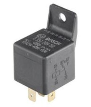
Bosch Relay 0332209150
Example of an Intermittent Duty Relay: A
relay (also contactor) which is switching a very high current, such as the
Starter Motor current, will typically have a very beefy coil (or even two, see:
Starter Solenoid), and will
draw such a high current in order to do its function, that it would never
survive the associated power dissipation if this were to occur long-term.
A Starter Solenoid needs, and requires, time to cool in between power-ups, or it will cook itself to death. I found that Solenoid
current is 10A with a momentary inrush many times that. Calculating dissipated
power from that value using Ohms Law (P = I X V), we get a whopping 120Watts
(recall that you wouldn't want to touch and leave your hand on a 100W
incandescent lightbulb)...ouch! Temperature of a continuously powered
Solenoid would similarly continue to climb until something was surely
damaged....that the Solenoid and Starter survived virtually continuous
energization (for multiple minutes anyway) while
Klaus Ludwig drove Porsche 962
No. 010 half a lap to the pits on the Starter Motor at Lemans 1988 is a
testament to the Bosch equipment, but I wouldn't make a habit of it!

The Bosch Starter Solenoid...
intermittent duty, but with lots of margin in a pinch!!
-----------------------------
Links:
In the application shown above, the Ignition Slave Relay is necessary to
control power, and Terminal 87 (Normally Open) is used. When
installing a Headlights-On Reminder, Terminal 87a (Normally Closed) is used
when Ignition is OFF, to switch Chassis connection for use by the circuit.
Note that separate relays would have to be used as one switches power, the other
switches chassis. See also:
http://www.sw-em.com/electrical_upgrades-buzzers_and_beepers.htm
Good Relay info:
https://www.linkedin.com/pulse/automotive-relays-fundamentals-testing-kiril-mucevski
The Ignition Slave Relay is also a good supply for audio power
amps...which seem to draw lots of stand-by power...if they are powered by the
Ign Slv Rel, one wouldn't even need to worry about turning it OFF! See:
http://www.sw-em.com/Battery%20Notes.htm#high_parasitic_load_audio_amp
-----------------------------
Note: I have added the Ignition Slave Relay into
the
Marked-up Wiring Diagrams of the 122 and
Marked-up
Wiring Diagram of the 1800 on the
Wiring Diagrams and Related
page.
-----------------------------
This information is Copyright © 2019. Ronald
Kwas. The terms Volvo and Bosch are used for reference only. I have no affiliation with
either company other than to try to keep
its products working for me, help
other enthusiasts do the same, and also present my highly opinionated results of
the use of their products here. The information presented comes from my own
experience and carefully considered opinion, and can be used (or not!), or
ridiculed and laughed at around the watercooler, or worshipped, at the readers discretion. As with any recipe, your
results may vary, and you are, and will always be, in charge of your own
knuckles, and future!
You are welcome to use the
information here in good health, and for your own non-commercial purposes, but
if you reprint or otherwise republish this article, you must give credit to the
author or link back to the SwEm site as the source. If you don’t, you’re just a
lazy, scum sucking plagiarist, and the Boston Globe wants you! As always, if
you can supply corrections, or additional objective information or experience, I
will always consider it, and consider working it into the next revision of this
article...along with likely the odd metaphor, or analogy (see above!) and probably wise-a** comment.
