
Amazon Tail Light Assembly.
Amazon Tail-light Fixture Restoration Notes
11/08,
Revisions 10/15 - R. Kwas (changes on-going)
[Comments Added!]
------------------------------------------
General
Removal of the Fixture from
Vehicle
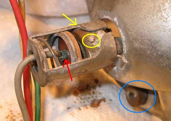
Amazon taillight
mounting screw in current path
Mechanical Refurb and Improvements
Preparing for Soldering
Electrical Refurb and Impovements
Optical Refurb and Improvements
Final Assembly
Lens Considerations
Bench Test
Installation onto
Vehicle
Considering
LED Replacement Lamps
Thermal Blinker Element
--------------------------------
Improving Visual Signature when Braking
Third and Strobing Brakelight Notes
--------------------------------
Links to Discussions on the Subject
Previous Owner Service and "Special Engineering"
--------------------------------
Amazon
Tail-light Fixture Maintenance
Practical
Application of ACZP
--------------------------------
General: Amazon Tail-light fixtures have the logo “Robo” (for Robert Bosch) and number 670614 stamped into them. They are made of simple formed sheetmetal with a plating which is mildly reflective when new and only slightly more reflective, after forty years of age and surface rust, than the background of gas station Elvis-on-Velvet-paintings [Reference 1]. Since the taillights are quite small to begin with, I thought it was time to show how to clean them up, and get the most light out of them possible. This really is a safety issue. I have thought about modernizing them with LEDs, but that is not as simple as one might think, because of the inherent differences between very narrow light output beam which these have (it's not enough to just plug in replacements, see also: Considering LED Replacement Lamps below!), so this is left for future consideration and for an article for another day!
Amazon Tail Light Assembly.

Excerpt from Wiring Diagram.
Note: Taillight fixture wiring color codes for both sides are the same, and only
upstream of the incoming connector (Junction Unit) is the Left is
Green and Right is
Blue color coding used for directional blinker circuits.
This allows fixtures to be interchangeable, side to side, and still keep the
color codes (except of course at the very end, between Junction Unit and the
fixture on the right).
A number of causes exist, which can all contribute to poor lamp electrical performance. They just about all involve poor connections in the current path which would serve to decrease voltage at the lamps themselves. I have highlighted these, and they are all covered here. The plan was to make all electrical connections in the current path as good as possible, and to also improve the reflectivity of the fixture to make best use of the maximum light output. When finished, I was quite happy with the effectiveness of the finished product during BenchTesting, considering it took a mere two hours to complete one fixture (not including removal from vehicle), and I expect this renewed effectiveness will last for a good long time!
Removal of the Fixture from Vehicle: I used a loose, spare fixture for this article, so I didn’t first have to remove it from the vehicle, but removal can be quite difficult itself given corrosion of the hardware, and possible stripped Phillips screwheads (29, 30) at the lens. Before any attempts to remove, and possibly doing more damage, I highly recommend applying penetrant to the upper and lower threaded (brass) inserts and bolt from inside the trunk, into which the lens bolts screw, a week, then again immediately before turning the screws! If the Phillips slots of the securing screws are bunged, it may even be possible to double-nut the back end of screws in the trunk to get them to start turning. Once the lens and chrome bezel have been removed, the fixture itself is held to the body by two tiny selfthreading screws (31).
These lowly two screws (31) are in fact quite important in that they are also the current carrying return paths for all lamp currents...if they are not particularly snug, you have just found Cause One of the reasons the lamps were not at their full brightness! After also unplugging the associated hex electrical connector (as in six, not as in bewitched, 28), the fixture can be removed. Once removed, the fixture may look similar to this one:

Before Pic of a reflector as it might look when first removed from vehicle...not
so pretty!
It doesn't look much better from the back side! Yellow
shows lamp locking pin is not
even in it's recess, and wire end at red looks pretty grodey too. Blue
highlights the lower brass insert .
Mechanical Refurb and Improvements: There is not much to the reflectors
mechanically, but rust and / or green and white stuff in the lamp sockets can
make the lamps difficult to remove or install, to say nothing of the poor
electrical connection which it is likely providing...
Cause Two for poor lamp function. A
penetrant will help with removal of corroded lamps...having access to the socket
and spring from the back also helps. In my spare sample, the lower (backing)
lamp was apparently corroded into place so well by dusty white corrosion, that
the glass envelope broke before it would budge when the last person tried to
remove it...I resorted to ripping out the remains none too ceremoniously with
needle nose pliers,
but I kept all force and damage to lamp base to save socket! The
crimped-on wire termination was missing when I finally got it out!

Removing remains of a broken lamp base from socket.
The socket base contact is found to be missing.
The folded over sheetmetal tabs of the socket, where they lock the socket to the reflector, are also subject to corrosion. This is definitely in the current path so will cause a subtle, easy to overlook electrical resistance which must be eliminated. I did not take this apart, not wanting to cause more damage than good, but simply prepared the outside surface for soldering also by wire brushing with a high-speed hobby-grinder with wire wheel attachment (Wear eye protection!... the fine wire bristles are miniature arrows as they are flung off the wheel at high speed!).
Preparing for Soldering: Once I had a clean shiny surface, I used a miniature butane gas torch to get enough heat into the joint to get proper solder flow across the gap, making a Gas-Tight-Joint and pretty much incapable of developing a resistance to lamp current...EVER again! Cause Three eliminated!
See also: http://www.sw-em.com/Wiring%20Notes.htm#Soldering_Notes

Preparing socket tabs for soldering by wirebrushing (red).
Yellow is critical lamp locking pin recess which must be clean and shiny.

Soldered lamp socket tabs (reds) make for an optimal long-term connection.
Lamp locking pin recess is shiny clean and likewise ready to make a
perfect connection.
Electrical Refurb and Impovements: All wire terminations connecting to the lamp contact should be soldered. This will assure the best connection between wire and crimped-on terminal. But with all the surface corrosion present, it will likely take some time for the flux of a quality lead/tin solder (like Kester brand 60/40) to cut through, but a good joint from wire to crimp termination must be established! I purposely left a small mount of solder on the part of the crimp which protrudes over the insulated disc in socket and which connects to the solder contact at lamp base. This eliminates Causes Four and Five!

Soldered Wire ends assure proper longterm connection to
lamps.
Missing end is replaced with a crimp terminal custom cut, bent to shape and soldered.
Although the entire round base of the lamps is in the socket, and theoretically making contact all around, fact is that the tiny recess of the socket which receives the locking pin of the bayonet lamps is really the predominant current carrying path because this joint is where the pressure of the spring in the socket is concentrated. It must therefore be cleaned to a shiny metal perfection! I used a micro wire brush for this, but a hobby knife or emery board will do nicely. When a lamp is reinstalled, the use of Anti-Corrosive Zinc Paste (ACZP) on lamp bases as well as this surface of the socket (especially the locking pin of lamps) will keep the connection protected and conducting at its best for a long time. Cause Six!
After this complete treatment, I expect the lamps will burn out before they need to be moved to clean a poor connection, and get them working again!
Optical Refurb and Improvements: After it is assured that the lamps will be working at full voltage, the light that they emit needs to be reflected out the lens and not eaten up in the fixture [Cause Seven]. The best thing is a mirror finish, but since my brother-in-law doesn’t own a plating company, I decided on the next best thing to optimize the reflector...I used a layer of stick-on, highly reflective, self-adhesive (real metal) aluminum tape. I chose this shiny tape over silver or “chrome” (not really!) paint, whose reflective characteristics have never impressed me.
I used 60 Grit to remove most of the toughest surface rust from the reflector, leaving a decent surface for the aluminum tape to adhere to. The round wire brushes intended for prepping the inside of 1/2" copper plumbing pipe before soldering, worked nicely for cleaning up the inside surface of the lamp sockets. After removing most of the surface rust present and cleaning with carb cleaner to get the best adhesion, I applied 1 1/2" wide self-adhesive (real) aluminum tape in horizontal stripes starting from the bottom with a slight overlap (like shingling a roof...water runs off not in). The thin metal stretches so can be burnished into the complex shape of the reflector...overlaps of the thin metal are not the end of the world. Beware: This is real thin metal which is capable of slicing skin just like a blade! Shop gloves will prevent slicing and dicing yourself... Once the new reflective surface is in place, a hole can be cut for the lamp socket with a hobby knife, and edges trimmed with shop scissors.

Self-adhesive alu foil is highly reflective, and from the
light pattern,
it's clear that the original concave shape of reflector was really quite good!
Final Assembly: Installation of the (cleaned up) lamps is naturally with a light film of ACZP on the entire base, and a dab particularly on the locking pin and base contact(s). Install normally, being aware that the middle lamp is a dual filament lamp which has its locking pins at staggered levels and only inserts and locks in one position.
Lens Considerations: Over the production run of the Amazon and considering the many countries it was delivered in, the metal base of the taillight assembly and associated lens styles underwent something of an evolution, from two section Red over Red, to three section Amber over Red, over White. As far as I know, only in the United States did the brainiacs of the DOT allow the Directional Indicator be the same color as the Brake Light...this gave designers of vehicles the freedom to make the Brake Light filament double as the Directional Indicator (but results in poor differentiation of the two). I much prefer the three separate section Amber over Red, over White lenses, as each function has its own filament and color, there is little chance that the amber Directional Indicator color cannot be differentiated from the Brake Light red, and so be overlooked. In order to keep section definition, and keep light from splashing to the adjacent section, a (mostly opaque) divider is present in the lenses, but adding some of the reflective metal tape on both sides of the divider will optimize its function.
Bench Test:
I assembled a new three-color lens and chrome bezel onto the plate and connected
power to each lamp. I was quite happy with the overall result at a nominal
12V...I expect the result in a running vehicle (with upwards of 13V system
voltage while Charging System is contributing power and pulling voltage up) will be even better. Frankly,
with this renewed level of performance, I don’t see much reason at this point
for changing over to LED light sources!...but below is some discussion on this:
Considering LED Replacement
Lamps!
That was rewarding in it's effectiveness and actually fun as restoration projects go!
 |
 |
After Pic of the refurbed and improved Amazon tail light fixture
...and that's not even the brighter brake light energized!
Installation onto Vehicle: Use ACZP on six conductor connector terminals, two tiny mounting screws and finally two bezel screws...that should satisfy for a looong while.
-----------------------------
Considering LED Replacement Lamps:
Excerpt of a posting of mine
[my comments and additions to what was
not part of the original posting]
(Link to Thread:
http://www.volvoforums.org.uk/showthread.php?t=232356&page=3 ):
Incandescent Lamps are (essentially) pinpoint,
omnichromatic [Full-specturm!] light sources (with light going in every direction), so 1.
Reflectors are necessary to redirect the light going in the completely wrong
direction and send it out the Lens, and 2. Lenses are necessary to filter out
all but the color we want (our Lenses are quite transparent and so do very
little directing).
LEDs on the other hand already are monochromatic emitters so we don't need to
filter then to get the color we want (we simply install the right color LEDs to
begin with), but they have by comparison an extremely limited cone of
illumination, so in order to get a similar source illumination, we would need to
essentially cover the surface of much of the reflector to do the equivalent
lighting and directing of light. [The
1157 equivalent lamps available as shown below, are an attempt at making a
pseudo pin-point source
using LEDs, so that major rework of the reflector is not necessary.] This would be tricky and will need some experimentation
to get right...it's on my list of ideas and projects...
LEDs certainly have advantages in how fast they light after voltage is applied
(instantly in comparison to incandescents), and how little current they take (a
third of incandescents [actually even
less than that...down to as little as one tenth! Ron]), but to change a
vintage car over effectively will take some experimentation...I suppose one
could simply buy some of those single and double element replacements with the
multiple LED arrays and try it...just be sure to do some real-life road tests to
assure good visibility from various viewing positions behind...our Taillights
are small enough...you wouldn't want there to be less...the point is to
improve our visual signature!...oh, and since LEDs don't draw the same
amount of high current as incandescents, the Blinker Element
needs to be changed
from a Thermal Bimetal type to an Electronic one...
Another excerpt of a posting of mine, to thread: LED
Tail Lights:
(Link to Thread:
http://forums.swedespeed.com/showthread.php?502921-LED-Tail-lights&p=6612186#post6612186
)
"LEDs are a very different animal from an electrical
standpoint (lower current, higher efficiency)...and from the light properties
standpoint (virtually instant turn-on, among other things)...even mechanical
insensitivity to vibration... all very desirable characteristics, so they seem
to have a lot going for them, and deserve our consideration....another crucially
important factor must be
mentioned: Incandescent Lamps are essentially a single Pinpoint
lightsource, for which the Reflector (which redirects light going into the
fixture and not heading out the Lens on its own, and this is a big portion of
total output) and Lens (which filters all but the desired 660nM Red color, with
a little redirecting thrown in...) have been designed and optimized.
Simply installing what I would call multi emitter tower or tabletop planar array
LED replacements, as shown below, DON'T automatically play well with the old
Reflector, because these replacements are not the Pinpoint lightsources the
Reflector was designed and intended for and they are not located anywhere near
the Reflector focal point...My point is: Don't simply plug these little magic
beasts in and think you are done...you might be decreasing your visibility...I
don't think that's the point of the exercise, and that's the last thing you
want!
It is very important to verify the effectiveness of your lighting fixture and
the light coming from a vintage Volvo Taillight from the typical position of a
driver following...closely, at distance, day. night, and to the sides. Check all
real-world operating conditions! "
----------------------------
Here is a bit of a theoretical comparison to illustrate the above:

I recently reworked this image to add different LED options, and show how the very different light they produce plays with the vintage fixtures designed for pinpoint sources. If you are considering installing LED replacements, it is imperative to perform real-world tests to assure the final outcome will give at least equal light performance, because this is not automatically assured! Remember...the goal is to improve your visibility, not decrease it!
It is therefore crucial to perform real-world tests to assure installing those LED replacements improve your visibility, not the other way around!

The LED Tower equivalent 1156/1157 lamp. LED emitters are distributed around the tower, and not in the same location in space (and more importantly, not at the focal point of the reflector!). I have yet to give these a critical test, so don't specifically endorse them at this time, but Nick R. (Maver1ck on VOC forum) has said he had a satisfying result installing them.

Tower LED Array.
LED Planar Array Source: With this style replacement (right), ALL light fires straight out from array (as shown in graphic above), and the reflector is mostly out of the picture and a don't-care...but as the only light to the side is strictly limited to the scatter coming from the edges of the Fresnel Lens, this severely cuts light output, and visibility(!) from the side.

Planar LED arrays for bayonet sockets.
Thermal Blinker Element: Link to Blinker Relay or Element Tech Article Page: Blinker_Relay_or_Element.htm
"Thermal Blinker Element" simply means that the blinker
element is an older style, which works on the basis of when lamps are ON, a
bimetallic element within the Blinker Element is thermally heated, causing it to
bend, opening a contact, breaking the circuit (lamps go OFF), no current flowing
allows the thermal element to cool back down, and bend back to starting position
remaking contact, restarting cycle... and this whole principle is a function of
the current going to the lamps.
Naturally since this lamp current is significantly decreased when
changing to LEDs, it throws a wrench into the whole operating principle of the
thermal element blinker element. ...this is where people simply "add resistors"
...these are essentially dummy loads which are added to the circuit in parallel
to the lamps, to increase the lamp circuit current, and bring it back up to a
high level which will allow the blinker element to work as intended. But this
is a true waste, because it truly wastes that additional current, strictly
turning it into heat so that the old blinker can still see the old (high)
current level and function as it did when incandescents were installed. A MUCH
better solution is to change over the blinker element at the same time to an
electronic one (which does not use the "thermal element" technology, but an
electronic timer to give the cyclic blinking). These are available and this is
is a one-time expense. There are two-pin types or three-pin types of blinkers,
so it's best to bring yours into a parts supplier, tell them you want an
equivalent electronic one and match it up, then try it to see it it plays well
in a particular vehicle.
-----------------------------
Improving Visual Signature when Braking:
Third and Strobing Brakelight Notes
-----------------------------
Links to Discussions on the Subject:
Thread about improving taillight performance : http://www.brickboard.com/RWD/volvo/735472/444-544/brighter_tail_signals.html
Thread about LED taillights: http://www.brickboard.com/RWD/volvo/1120248/120-130/anyone_running_led_tail_lights.html
-----------------------------
Previous Owner Service and "Special Engineering".
Here is what the new owner found when he was less than happy with his Amazon Tail-lights, so removed the Lens for the first time:
Donald Pangburn picture used with his kind permission.

The only way these bulbs could emit any less light is if they were
disconnected...!
Extremely dusty bulbs don't emit much light! This level of dustiness is the result of lots of outside dust getting between Lens and Reflector due to a poor seal [...says the master of the obvious!], but carefully studying the picture, one can see this is in turn a result of incorrect assembly, which is maybe not so obvious!
The Reflector should be installed from behind the metal mounting flange, and from inside trunk. Since the assembly has its own Hex-Connector about a foot back for the Reflector assembly, its not very difficult to separate it from the car to locate it correctly. This will change the way Seal and Lens, and Chrome Lens-surround fit and play together, and also eliminate the dustleak...but before the new owner reassembles correctly, he might want to (at least!) clean up and optimize the light properties of the reflector, see above! [...and now, also below!]
-----------------------------
Reference Information:
Roffe and Bjorn test Directional Indicators:
https://www.youtube.com/watch?v=LvLaky3eJjo
-----------------------------
Amazon Tail-light Fixture Maintenance:
Jun-2022, R. Kwas (changes on-going) [Comments Added!]
If a complete Rear Fixture Rework is not necessary or a simple preventative maintenance will suffice, or like me in this case, you really just wanted to replace the deteriorated Rubber Seal/Gasket, here is the quick version, which did not require the fixture to be removed from vehicle...the entire process took less than an hour!
Tools used: Philips No1 and 2 Drivers, Super Lube (rubber compatible lube/preservative), Tri-Flow light PTFE filled oil, ACZP, Carb Cleaner, paper towels.
The process presented here can naturally be adapted to other models...

Crustification of rubber Seal calls for replacement!
Lens and Chrome Surround removal.

The application of some Tri-Flow
penetrating lube onto the backs of the two securing screws (from inside Trunk) in their threaded
inserts, allows a painless removal of the screws. The Reflector is found to
be less than as new in condition, so it will be improved.
New rubber Seals, as well as stainless steel screws are available!

A pre reassembly protective anointment of the entire replacement Seal with a
film of Super Lube
(Repackaged here by the author into a syringe for pinpoint application).

Out with the old, in with the new!

While the Lens and Chrome-surround are off, the reflector is cleaned in
preparation for application of self-adhesive reflective alu tape.
Note also the position of reflector behind the body sheetmetal, unlike the incorrectly located one which prevented the Seal from working as intended, allowing lots of dust onto the Reflector and Bulbs. See: Previous Owner Service above.
Spot improvement of the reflector.


Six pieces of adhesive backed alu tape are prepared, applied, and burnished into
place in the reflector areas.

Lamp bases are cleaned of any corrosion in preparation for reinstallation.
Practical Application of ACZP:

Before installation, Lamp-bases and contacts get an application of
ACZP, of
course!

The new SS securing screws (Philips No.2) look a lot nicer too...! Threads
get a dab of ACZP
too!

Fixture securing screws (Philips No.1) are checked for snugness (Reminder:
These are in the lamp return current path so must provide a good electrical connection
between body and lamp fixture (Reference:
Mounting screws in current path. ), and while accessible, the body gets
a good waxing, before it is once again inaccessible...

The new installed Seal is somewhat unruly while securing Lens/Chrome-surround, because the protective film also acts as
a lube, which allows it to slide into every position but the preferred...but if
one prevails, maybe helped by a plastic edge tool (or a screwdriver with a taped
edge) for helping position the Seal, one can persuade it into its proper
place...
After: That looks a lot better!

A quick light-check after the procedure was complete, went without a hitch, and I didn't take any "Before (Lamps energized) Pictures" to compare, but the light output must surely be better! This was fun!
------------------------------------------------
External material sources are attributed. Otherwise, this article is Copyright © 2008-2026. Ronald Kwas. The terms Robo, Robert Bosch and Volvo are used for reference only. I have no affiliation with any of these companies, other than being a satisfied customer and occasional mechanic on their products, in order to keep them working for me, and to help other enthusiasts try to do the same. The results presented here are from my own experience, and can be used (or not, and used strictly for your amusement!) at your discretion. As with any recipe, your results may vary! As always, if you can supply corrections, or additional objective information or experience, I will consider it, and consider working it into the next revision of this article...along with likely the odd metaphor and maybe wise-a** comment.
You are welcome to use the information here in good health, and for your own non-commercial purposes, but if you reprint or otherwise republish this article, you must give credit to the author or link back to the SwEm site as the source. If you don’t, you’re just a lazy, scum sucking plagiarist...the Boston Globe wants you!

