
Fuel Gauge 1800 Information and Notes
First published: Nov 2019 R. Kwas Revisions On-Going
[Comments Added]
This page covers Fuel Gauges for both early (carbureted) and later (injected) chassis, which are quite different in their function and operation.
Carbureted 1800 (P and S) Fuel Gauge Notes
Troubleshooting Notes
Fuel Sender Notes
Injected 1800 (E and ES) Fuel Gauge Notes
General Operation/Power
Theory of Operation
Checking Fuel
Gauge Calibration
Troubleshooting Fuel
Gauge and Common Issues
Possible Circuit
Interaction
Sender Considerations
Links
James R. repairs a
Non-Functioning 1800S Fuel Gauge
Reference Information
Smiths Thermal
Instruments, fitted to the 1800E and ES cars
Link to Document published in 1966 (good info!):
Smiths - The Care of Instruments
Link to 122 Fuel Gauge Notes, including troubleshooting: Fuel Gauge 122 Information and Notes
-----------------------------------------
Carbureted 1800 (P and S) Fuel Gauge Notes: The Smiths supplied 1800 fuel gauge (early, carbureted) is different from both 122 (based on the VDO supplied Drehspulinstrument) gauge (but not in operating Principle, see below!) and later (injected) Voltage Stabilizer associated gauges of the E and ES vehicles, therefore these three gauges types are considered separately below.
Slight variation in the face exist between the pre Chassis No. 7000, and post Ch. 7000, but the internals of gauges are the same, and in operating principle, similar to gauge of the 122. See also: Drehspulinstrument
-----------------------------------------

A page from the Factory Manual [correction for Fig. 2.3: Connection for
Ignition Power (not "positive terminal of battery"!). Fuel Gauge is
an Ignition function...why would you want it ON all the time, draining
the Battery? You wouldn't!...more auto-electrical wizardry courtesy of
Lucas? ]

1800 Fuel Gauge and circuit detail.
Full Indication: With Ignition ON, indication at Gauge should correspond to Fuel Level in Tank, but if it goes to Full, and stays there, even if Tank might be something less than full, it indicates an open connection somewhere, anywhere in the Sender line...from the wiring itself (rare but possible), the connection to chassis (including Sender electrical connection to Tank, and Tank electrical connection to Chassis), or within Sender itself. A "Generous or Non-Linear Fuel Level Indication" on the other hand, can be an indication of a less than perfect connection in the Sender circuit, with this in-line Resistance being added to the R of the Sender.
If an Indication of Empty occurs (even with a Tank known to not be empty!), it can be that Gauge is not powered (open power or chassis connections), OR a Sender cable shorted to chassis, or even a non buoyant Float (see below!).
------------------------
As noted, 1800 and 122 instruments are similar only in operating principle. Picture below shows two Magnetic Coil Assemblies fixed to the housing, and generating magnetism at right angles. In the 122 instrument, they are part of the rotating Needle Assembly, see: Drehspulinstrument. Range of Resistance of the Sender does differ between the two instrument suppliers. See below!
Subsequent pictures by James R. and used with his kind permission:
[Very apparent in the following picture is also the Instrument Chassis connection which has been shown to be quite important! See: http://www.sw-em.com/Two_Wrongs_Make_a_Right!.htm ]

What the 1800 Fuel Gauge looks like from the business end, installed in a
Dashboard. Red/White wires are Instrument Lighting (Lamp in holder is a
friction-fit, and simply pulls out, for checking or bulb replacement),
(Double) Greens are Ignition Power from Fuse 2, to
B Terminal of Instrument, Green/Black is the Sender
connection to T Terminal of
Instrument, and (double) Blacks visible are some instrument chassis connections
(these are quite important for function of instrument, and may be located on Fuel Gage, or elsewhere)...depends on if it was raining
that day in Britain...
Reference also Wiring Diagram 1800: https://www.sw-em.com/Wiring_Diagrams_and_Related.htm#1800_Wiring_Diagram

Tools used to gently nibble (by bending) away at the Chrome bezel to allow gentle
removal of it, and gauge face (notice the generous and repetitive use of the
word gentle here...this is not by accident!). Note evidence of the bending on the instrument
edge to allow this. Note also slotted holes (at
Yellows) for precise position
adjustment of the Magnetic Coil Assemblies during calibration (see text below!).
There is evidence of a white lacquer on securing nuts. Don't loosen or
reposition these, but verify securing nuts are snug and have a dab of locking
paint. In the case of James' instrument, something in this system failed,
allowing coil assemblies to move out of position, which caused a complete
failure (non-function, but not terminal/death!) of the instrument.

Internals of gauge exposed.
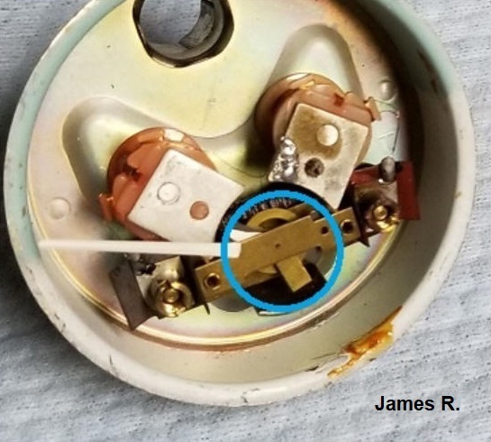
Blue circle highlights movement
arc of Needle Assembly, and matching arcs on the endplates of Magnetic Coil
Assemblies are clearly evident. Precise position of these determines
magnetic influence on the Needle Assembly and instrument calibration. They
were positioned and locked into place at the factory, and should not be moved by
mere mortals!
-----------------------------------------
Although the operating principle of the Amazon and 1800 Fuel Gauges is similar, the operating range of the 1800 Sender, at 3 Ohms (Float Down!) - 80Ohms (Float Up!), is different from that of the Amazon Sender.

1800 Tank Sender (Replacement type with plastic Float)
From the Brickboard Thread: Rusted out float on P1800 Smiths Fuel Sender 1800 1964:
https://www.brickboard.com/RWD/volvo/1677421/1800/rusted_float_p1800_smiths_fuel_sender.html
Pictures by J Graham Coutt.

The way JG found his Sending unit after removal from Tank.
Symptoms were
an Empty fuel level indication on gauge, even with a full tank.
That makes
sense, as the Float clearly was low in the buoyancy department.

JG's solution was to fit a brass float originally from a Mustang sender.
Coil of resistance wire in the upper compartment is apparent.
While Sender is on the bench, cleaning and inspection of the slider contact area are good practice, as is lubing this (wear) area with some Mobil 28 synthgrease. This grease is light in body, so easily displaced by the Slider allowing normal operation, but serves to lube the Slider contact area, minimizing wear.

Close-up of the Sender showing coiled length of resistance wire.
Highlighted in Yellow is the Slider, which is connected to the Float by way of the
rod,
which can be bent slightly to adjust gauge indication.
-----------------------------------------
Injected 1800 (E and ES) Fuel Gauge Notes: These Fuel Gauges are supplied by the Voltage Stabilizer, and are quite different in operation, and the way they play with the Sender, from the earlier 1800 electro-magnetic style...don't mix the two up!
General Wiring Diagram Excerpt showing all the Instruments, including the Fuel Gauge. Some Instruments are supplied by the continuous 12V Instrument Power (Ign, by way of Fuse4), and the Smiths Thermal Instruments are supplied by the Voltage Stabilizer putting out 12V cycling (10V long-term average), as shown here:

1800E/ES Instrument power supply wiring.
Green is fused Ignition,
Instrument Power,
Blue wire is VStab power, supplying
Oil and Coolant Temp as
well as Fuel Gauges .
Isolated Wiring Diagram Excerpt for Fuel Gauge only:
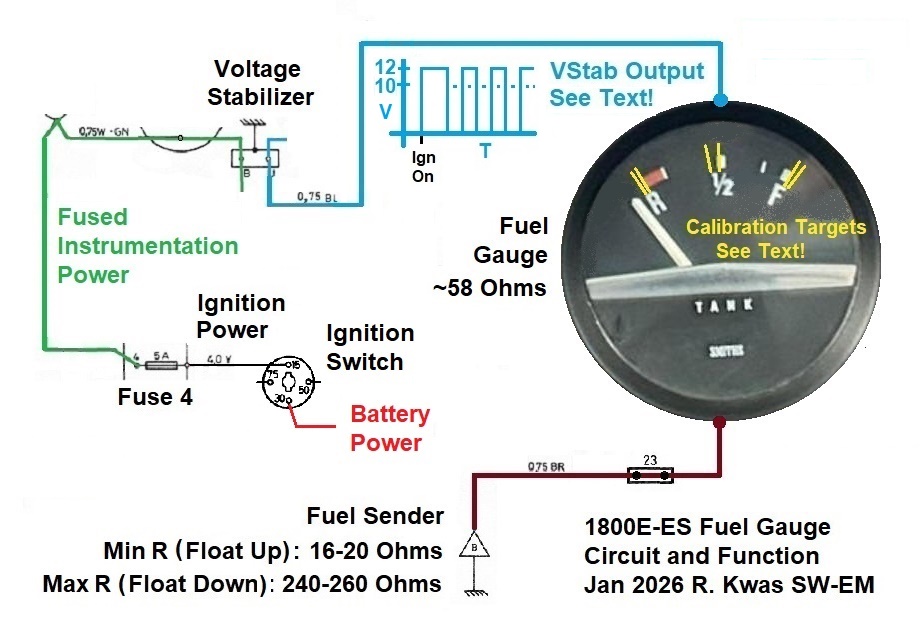
1800E-ES Wiring Diagram excerpt for the Fuel Gauge and associated circuitry.
I have highlighted
Calibration Targets present
on gauge faces, used during manufacturing for adjusting and
checking accuracy...and we can use them again, for the same purpose!
General Operation/Power: 1800E and ES Fuel Gauges, are supplied by Instrumentation Power Fuse 4 with a Blue wire, by way of VStab, so power measured on the Blue wire supplying the Gauge (with Ignition ON) will be not a steady 12V, but the slowly cycling output of the VStab with a 10V long-term average. See: Voltage Stabilizer
Theory of Operation: The Gauge is a thermal type, similar in principle to the Coolant and Oil Temp Gauges. [No, more than that! Actually internally identical in construction and function! The only thing different between the three Gauges supplied by the VStab, is what the Gauge faces are calibrated in, and their Sender Resistance. See also: Reference Information: Smiths Thermal Instruments] By conducting a sensing current, varied by the Sender and what it is monitoring, in the case of the Fuel Gauge, the Tank Float, through a Heating Element wrapped around a bimetallic element, moving the Indicator Needle, the Gauges have a deliberate slow response. This intentional slow response prevents a jittery Indication, especially for the fuel level, which can vary as it sloshes around, making an undampened instrument distracting. The Heating Element within the Gauge should measure approx 58Ohms, measurable across the terminals of the Gauge. The Sender R varies with the Float position, as noted in the graphic. Minimum Sender R sets the maximum Gauge current to about 0.130A (reference calculations below). Volvo's factory "Green Book" service manuals specifically warn against testing the Gauge by shorting the Sender Wire to chassis, as this would pass an even higher and damaging current.

Thermal Gauge internal workings, the fine
Heating Wire is evident, wrapped
around the Bimetal element, as are the
(2) rectangular holes and slotted mounts, which allow movement for the
purpose of adjustment during calibration.
See also below: SW-EM
Calibration Check Potentiometer
Reference Info on Temp Gauge Calibration:
Link to
Gauge Calibration
Calculations:
Normal Operation Conditions of Gauge Current (I), V used is long-term average of 10V:
Float Up (Full Tank) Min Sender R: I = V / Rtotal = 10 / (58 + 18) = 10 / 76 = 0.13A
Float Down (Empty Tank) Max Sender R: I = V / Rtotal = 10 / (58 +250) = 10 / 308 = 0.032A
Worst Case (Fault Condition) Calculations of Gauge Current (I), Full Tank and Failed VStab, not cycling (14V output, steady-state/non-cycling):
I = V / Rmin = 14 / (58 + 18) = 14 / 76 = 0.18A (Calculated worst case power dissipation of heating element within Gauge: P = I2 x R = 1.8W This is not an extremely high amount of heat generated. It is therefore the authors judgment that this will not immediately damage the gauge, however could in the long-run affect/decrease it's calibration by overheating bimetal element.
Worst-Worst Case (Fault Condition): Sender wire is connected to chassis: I = V / R = 14 / 58 = 0.24A P = I2 x R = 3.38W! This is a high amount of heat and much more that I expect it can survive! The following detail of the internal Heating Wire on the Bimetal of the Gauge, shows unmistakable signs of "rattyness", where the insulation lacquer has been baked off the HW, at least partially. The next step would have surely been shorted windings and/or fusing open. It looks like the excessive heating was stopped just in time, before such damage occurred, but still leaving some damage in the form of the ratty insulation. Specific cause in this particular case is unconfirmed, but this could very well be a result of a failure of the V-Stab not cycling, resulting in the Gauge being powered by continuous ~14V when engine is running, causing in this collateral damage inside the gauge...or worse...a Sender Wire shorted to chassis (inadvertently or intentionally, by an uninformed troubleshooter), allowing maximum current through the HW and high power dissipation.

Result of an overheated Heating Wire in a Fuel Gauge.
Eugene T picture, used with his kind permission.
Checking Fuel Gauge Calibration: By disconnecting the Sender and substituting Reference Test Resistance values, one can check the calibration of the Fuel Gauge much like was performed at the Smiths factory. These tests can be performed on the bench, powering the Gauge under test by a 10VDC bench supply, and applying a Test Voltage (as also shown here for the Temp Gauges LINK) OR a Test Resistance (and calibration can be adjusted with a Cal Tool. See: LINK), OR for only checking the calibration with no adjustment possible (because of the contortions which would be necessary) while Gauge is In-Situ in a car and being powered by the VStab (Ign ON, Ign Coil [Neg] disconnect for duration of the test, to prevent Ign Coil overheating), and applying a Test Resistance in place of the Sender, as shown in this chart.
| Test Resistance Ohms (1W min) [These values are theoretical and will be verified and fine-tuned practically!] | Test Voltage applied (Alternate test method!) | Calibration Target | Note: When changing Test R or V. Allow 10 seconds for Indicator Needle to thermally stabilize, after which Needle can be checked to see if it falls within the Target range on Gauge Face, and calibration adjustments can be made. LINK |
| 250 | 2.0 | Empty | |
| 150 | 4.8 | Half | |
| 16 | 7.0 | Full |

Calibration Targets for Reference
Resistances or Voltages.
Troubleshooting Fuel Gauge and Common Issues: Failure of the VStab to supply power to the Fuel Gauge will result in the Indicator Needle never coming off the peg, that's the simplest, but also rare because VStabs themselves are quite reliable...it's just that their chassis connection sometimes is less than good, because it is by way of a Thumbscrew holding it on the back of the "Combined Instrument" (Speedometer)...it's good practice to make certain the thumbscrew is not loose, any time one has gone to the trouble and contortions of getting access to be back of the Instruments, because looseness will result in similar symptoms as a failed VStab, non-cycling, and high Gauge indications! (See: LINK ). But ANY failure to get power to the gauge will result in Indicator issues (including poor instrument grounding, and don't forget, as has been noted on other 1800 instruments, the chassis connection is not by way of a dedicated terminal and wire, but by way of the instrument cases and mounting clamps to Dashboard, see below! Poor grounds can also result in inadvertent interaction of circuits which normally would not interact in ways the author has yet to think of...and I can think of, and have seen, a few!! See: "Wacky Blinker Function"

Back of an installed 1800E/ES Fuel Gauge, picture kindly provided by Doug
Morrell, showing bracket and two thumbscrews securing it to
Dashboard...also evident is a terminal with a single black ground wire under
one of the Thumbscrews...I
don't know to which circuit
that wire provides a chassis connection, but
that groovy Thumbscrew looks to not be
fully snug, so, it sets up a condition for that circuit
to develop
symptoms, see below. These Thumbscrews MUST be well snugged, to prevent
problems later.
Doug Morrell picture used with his kind permission.
Possible Circuit Interaction: In studying this configuration and noting that the Gauge is illuminated by the Instrument Lighting Circuit (which has only one wire going to the Lamps, so also has its current return by way of the Instrument Housing and that straddling bracket to the dashboard), it might be possible for the Instrument Lighting to influence the Remote Circuit, as the two currents combine, if a poor connection to chassis develops! (Ref: LINK: Inadvertent Circuit Interaction )

Detail of possible circuit interaction, when Thumbscrew, which is supposed
to
provide a connection to chassis, is loose.
Fuel Gauge Lighting will interact with Remote Circuit, whatever that may
be...only your wacky symptoms will tell!!
Sender Considerations: As in the other Volvo models covered elsewhere on the SW-EM site, the Sender is mechanically mounted on the Fuel Tank, and the Tank is secured into the body with screws. In order for the Fuel Gauge to work reliably and accurately, both the Sender mount and Tank-to-body mounting must also have good (not loose or corroded) electrical connections! If they do not, the inadvertent R of a poor chassis connection is ADDED to the Sender R, resulting in a fuel level indication lower than actual. [...at least it's not the other way around, like on the 122 model, where this results in a "generous fuel gauge", which can leave us stuck...typically an additional series R in the Sender line of the 122, just results in Gauge non-linearity! See: LINK ].
Checking the Function and Calibration: If two fixed value Resistors of 18 and 250 Ohms (1Watt rated) are available for test purposes, these can be temporarily wired in place of the Sender, to check the Fuel Gauge action and calibration at two points of indication.
Alternately, I have made up several Sender Simulator Potentiometers and am making these plus instructions available for a modest rental fee for owners who wish to conduct a functional test including checking the Gauge Calibration. Contact me to arrange this!
SW-EM Calibration Check Potentiometer: With this device temporarily connected in place of the Sender, the calibration of an E or ES Fuel Gauge can simply be checked! Contact the author if you would like to borrow it, along with instructions for use, against a small deposit.

SW-EM Calibration Check Potentiometer set to mid-range, of travel, and
mid-range on Gauge under test,
showing 150 Ohms on the DVM. A 15 Ohm Resistor has been added to set the
absolute minimum R,
and never let it get to zero (the undesirable and forbidden condition of 0 Ohms [short]
to chassis)!
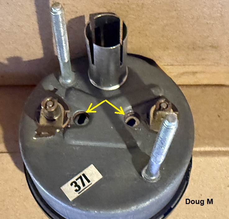
Doug Morrell has provided a clear picture of the rear view of Fuel Gauge on the
bench. The two calibration
openings are clearly evident
[after piercing through factory paper seal which may still be present].
He reports a strategically sized screwdriver worked well to diddle
the adjustment (the term diddle is used to emphasize gentle, small,
incremental adjustments!). After adjustments are complete, a bit of
electrical tape will exclude debris and new-home-seeking arachnids from the (for
them!) inviting apertures.
Doug Morrell picture used with his kind permission.

Internal view of a Fuel Gauge showing Heating Wire and
adjustment slots in the
mechanism, which can be adjusted to vary gauge
calibration. If you are going to attempt to adjust, note that the
adjustments are very sensitive, and also interact, so adjustments are
best made when one is not rushed, and marks of where adjustments were when one
begins, are suggested, so that one can have
a better chance of returning to the starting point...
Eugene T picture, used with his kind permission.
Note that the Gauge internals are mounted on an insulated phenolic carrier, so completely isolated from chassis...the ONLY connection of the fuel level sensing circuit to chassis is by way of the Tank Sender. The gauge illumination lamp current on the other hand, is returned through the gauge housing, as can be seen above the insulated carrier. This sets up the condition of Possible Circuit Interaction explained above.
[PLACEHOLDER FOR 1800E/ES Fuel Gauge Functional Checking and Power-Up Calibration Tests: I will be procuring a test mule sample Gauge and will add result of inspection and tests with Test Resistor Values set by a specially constructed SW-EM Calibration Potentiometer, which will be available for rent against a deposit.]
-----------------------------------------
James R. Repairs a Non-Functioning 1800S Fuel Gauge (early, carbureted): https://forums.swedespeed.com/showthread.php?610015-Fixing-P1800S-fuel-gauge
Apparently, the Magnetic Coil Assemblies on his gauge became dislodged and were out of position...he notes: "There was also a circle at the base of the needle with a similar diameter of the crescents, but my crescents were no where near lined up with the base of the needle. ").
My response to that thread
"Those pieces with the crescent shapes are the two Magnetized Coil Assemblies (at right angles to each other, this is the basis of both the 122 and 1800 instruments. Note in the 122 instrument, the coils are part of the rotating armature, in the 1800 instrument, they are fixed to the instrument case. See: https://www.sw-em.com/Fuel%20Gauge%2...spulinstrument), which act upon the Needle (more specifically, what the Needle is mounted to)...it sounds like mechanical securing of those coils became dislodged, so the magnetism was out of place and because of this, ineffective to work on the Needle as intended. By moving the poles to where it seemed they should be, you have brought back the function, but I expect the calibration will have less than its original accuracy and should not to be highly trusted until you get a few tank-fulls of experience with it! Congrats on the repair!"
------------
Link to another thread: http://forums.swedespeed.com/showthread.php?547874-Gas-tank-level-replacement-recommendations&p=6709266#post6709266
-----------------------------------------
Smiths Thermal Instruments, fitted to the 1800E and ES cars:

Since all three gauges are identical in internal construction, and their supply
voltage is also the same, it stands to reason that the only differences
necessary (or possible) for measuring different temperatures (or tank level),
and the only thing which changes for each Gauge, is the Sender R,
and this is accompanied by changing the labeling on the Gauge face. Also,
since the Oil Temp Gauge reads the highest of the two temp gauges, one can see
the starting (cold) temp R is a fairly high 3000 Ohms (in comparison to
the other R values), keeping gauge current quite low at low oil temps.
This explains, in part, why Oil Temp Gauges are often suspected as not
working...the other is the non-linearity of the R vs. Temp curve of the Sender.
See also:
LINK
Link to Document published in 1966: Smiths - The Care of Instruments
------------
Related to Reliability of Smiths Gauges:
Question: Where did workers fired from the Lucas factory go?
Answer: Down the street to the Smiths factory.
-----------------------------------------
External material sources are attributed. Otherwise, this article is Copyright © 2019-2026 Ronald Kwas. The terms Volvo, VDO, and Smiths are used for reference only. I have no affiliation with any of these companies other than to present my experience, and highly opinionated results of the use and care of their products, for the purpose of helping other owners keep their vehicles on the road, safe and reliable, and including ridiculing Lucas automotive electrics...because they brought it on themselves, so truly deserve it! (Reference Example: Proving Everything Bad you Ever Heard About Lucas) The information presented is my own, and can be used or not, or ridiculed and laughed at, at the readers discretion. As with any recipe, your results may vary, and you are, and will always be, in charge of your own knuckles, and future!
You are welcome to use the information here in good health, and for your own non-commercial purposes, but if you reprint or otherwise republish this article, you must give credit to the author or link back to the SwEm site as the source. If you don’t, you’re just a lazy, scum sucking plagiarist…so The Boston Globe wants you! As always, if you can supply corrections, or additional objective information or experience, I will always consider it, and consider working it into the next revision of this article...along with likely the odd metaphor and maybe wise-a** comment.
