Brake Failure Warning Valve
Notes
Sep 2026 R. Kwas [Comments
Added]
----------------------------
Brake Warning Valve and Switch
Additional Information:
Resetting the Brake
Failure Warning Valve Switch
Brake Warning Switches, new vs old,
damaged.
Details, and Pictures of Disassembled BWVS
Detail of Thrust Washer
Links to Referenced and Related SW-EM
Articles
Dual Brake
Failure Sensing from the Volkswagen World
----------------------------
Note: The terms Brake Failure Warning Valve, and Brake Warning Valve From the Factory Manual may be used here interchangeably!
Some of the material here was originally in the Tech Article: Two Wrongs make a Right! (Electrically Speaking), which involved unusual symptoms caused by interaction of BFWV and the Tachometer of all things! As usual, locating the root cause involved a poor chassis connection, but the troubleshooting process was interesting... As I have recently developed more details on the BFWV, I have gathered info for this new Tech Article, focused only on this unique component of the Dual Brake System, which senses when more than 142PSI (10kg/sq cm) of pressure exist between the two systems, and alerts the driver to this significant difference in the pressures, by way of the Brake Warning Indicator on the Dashboard. Brake system pressures are obviously produced by the force on Brake Pedal, so the pressure in both systems should be pretty much equal, but a significant difference indicates one system has failed, and immediate safe stopping followed by check-out and service/repair is called for!
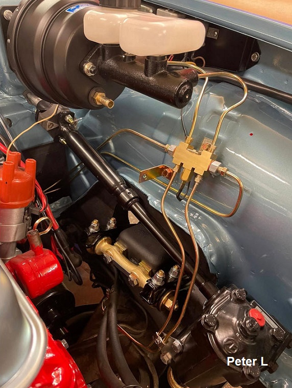
First class restoration work by Peter Land, with a great view of the Brake
System Distribution Block/Brake
Warning Valve...the two hydraulic systems are in view coming in from
the Master Cylinder, with differential
Pressure Switch between the two systems. Notice it is installed with the
Switch orientation pointing down.
Peter Land picture shown with his
kind permission.
From the "Green Factory Manual":
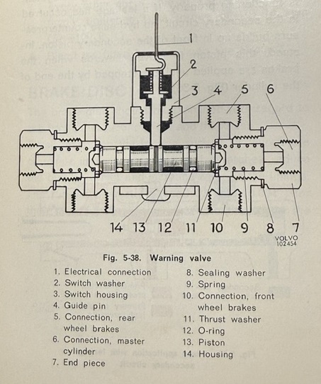
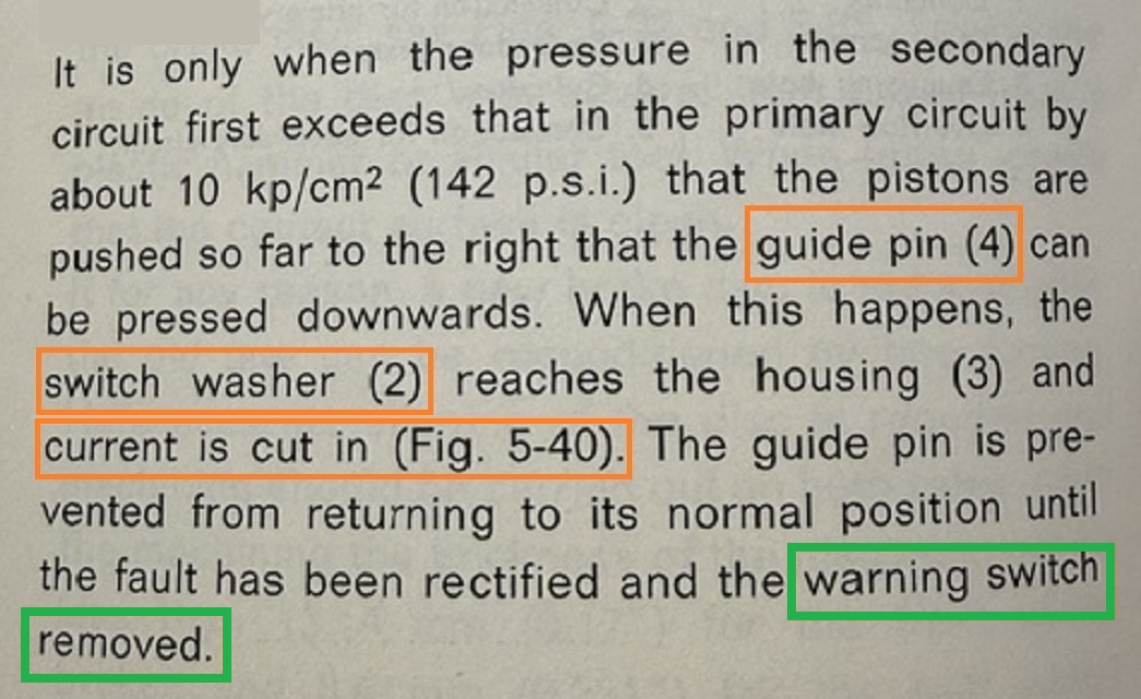
From the Factory Manual (for '71 1800E) a lot of good info, but also showing some
inconsistencies with the terminology
the reader will see
in these notes: Transfer Pin = Guide Pin,
Contact = Switch Washer,
Current
cut in = Current Flows.
Note also
that the manual does
instruct to remove the Switch in order to reset it!
|
|
 |
Brake Warning Indicators on 1800E and Amazons with dual Braking Systems.
Referring back to the Owner's Manual, this Indicator, when fitted in 1800E/ES or 122/123s with dual Braking Systems, is OR-tied Indicator, with either the Switch at the Handbrake OR the Brake Warning Valve Switch being able to light the Indicator by supplying a chassis return connection, after the internal shuttle moves to the side due to one of the two Braking Systems not making pressure.
See also wiring of Brake Warning indicator as implemented in the 1800E/ES: Wiring Diagram Excerpt Brake Warning Light
Brake Warning Valve and Switch:
Little magic...just a simple and effective way of sensing a pressure difference between the two braking systems...! Of course there is a precise pressure difference specified as a function of the counter-spring force vs. the cross sectional area of the Shuttle, and this is covered in the Green Factory Manual, but that is not necessary for a functional understanding of the BWVS here.
See also how VW does this in contrast.

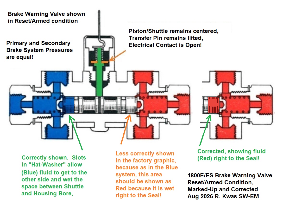
Inner workings of the Brake Warning Valve Switch,
in Normal and
Activated Conditions.
The Orange contact is shown
lifted from contact with conductive housing in the Normal Condition,
and in the Activated Condition, bridging from the external terminal to housing (chassis).
[I observe and have corrected an
inconsistency in this graphic, below! See:
Corrected Factory Graphic]
The Shuttle (Volvo calls it Piston, but I prefer Shuttle as it is able to move in either direction) within the BWVS, has moved to one side it needs to be reset after the cause is remedied and both Brake System need to be bled. By Loosening and withdrawing the Switch, Spring force re-centers it, but it MUST stay removed during the brake bleeding process, see also below),
---------------------------------
Additional Information:
Resetting the Brake Failure Warning Valve Switch:
It is easy to damage the nylon plunger of the Switch by not following the Reseting procedure and withdrawing it BEFORE the bleeding operation!
Shuttle inside Brake Warning Valve does have springs which SHOULD center it once Switch is removed, but if it is sluggish to move on its own (evident by the depressed area of Shuttle remaining in the hole, and for the Switch Plunger to stay extended and grounded, enabling the Brake Indicator), a tap or two on the Brake Pedal might help unstick it. [...but having seen the Springs (below!) which supply the centering force, I would say these are substantial, and knowing the brake line pressure are also quite high and will easily overcome the spring-force, so if the Shuttle does not re-center on its own during the bleeding operation, a disassembly and inspection of the assembly as to the cause is definitely in order (and maybe a cleanup and rebuild with brake-fluid compatible grease)!]
Brake Warning Switches, new vs old, damaged.
Neville Britto picture used with his kind permission.

New BWS on left and used one on the right, exhibiting definite signs of a
damaged/sheared/shortened transfer pin/plunger,
consistent with not having been withdrawn before bleeding operation, as
Eric warns!
Preventing damage to the protruding plastic pin: I thought the following info was important enough to pass along verbatim! The highly experienced Volvo Specialist Eric H. "Planetmen" on the vintage Volvo Fora suggests the switch should (NO MUST!) be removed BEFORE the brake bleeding operation! He says in this Thread ( https://www.turbobricks.com/forums/showthread.php?t=337880 ) on Turbobricks:
"...critical
procedure is to remove the switch BEFORE the brakes are bled and to only
re-install the switch
after the
brakes are bled.
The plastic
shaft that actuates the switch gets damaged each time the shuttle assembly
inside the warning
system goes
back and forth.
This chops
off small pieces and shortens the plastic shaft to the point where it is not
long enough to cause
the switch to
break its internal contact that would shut off the dash light. "
Details, and Pictures of Disassembled BWVS:
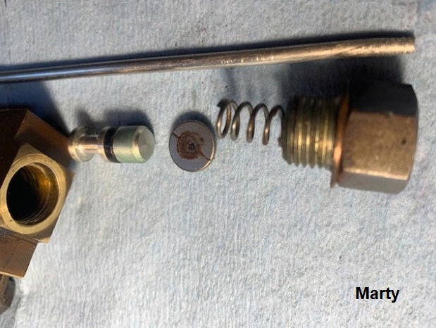
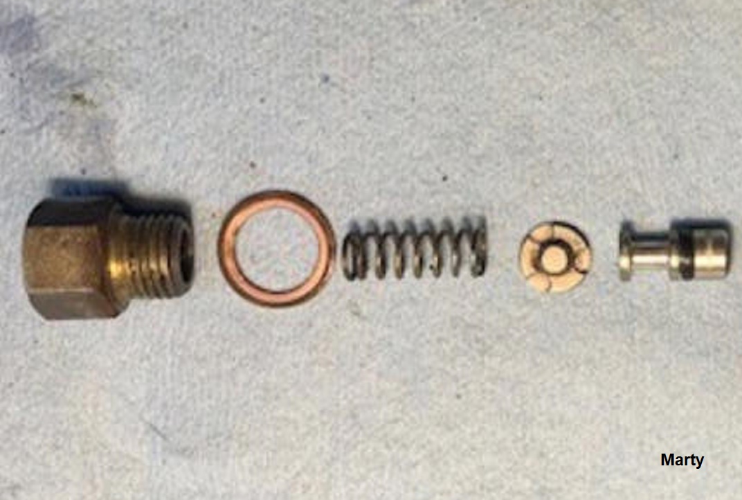
Marty, of the 1800List has kindly provided pictures to allow seeing details...
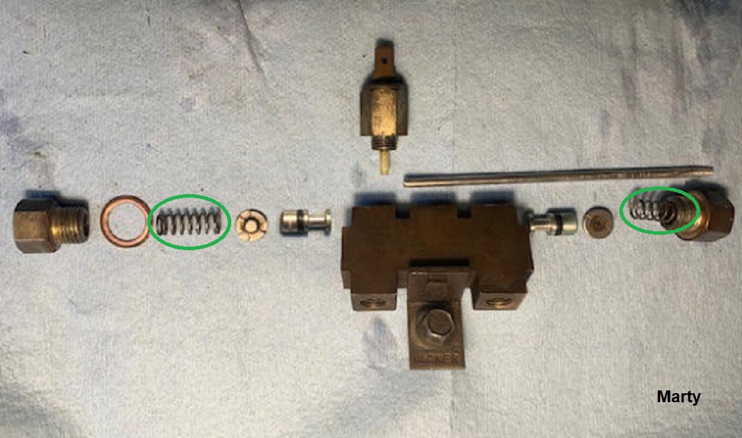
A Brake Failure Warning Valve Disassembled and laid out for inspection.
The Centering Springs are
substantial! The rod also visible is not part of the assembly, but was a
soft aluminum rod used to push the innards from the bore.
Shuttle/Piston in the Armed Position (Housing omitted for clarity):
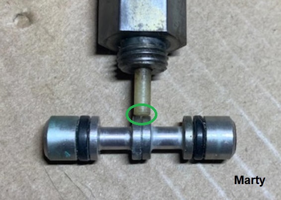
Shuttle centered on shuttle major
diameters with (nylon) Plunger Switch depressed and "armed" (so
contact in the switch lifted from seat and open!), ready to trigger when
shuttle moves enough to allow plunger to fall into minor diameters. Note:
This would require enough pressure difference in the two systems, to cause
Shuttle displacement to overcome the centering force applied by the springs at
either end (not seen in this picture), so this mechanism does have a level of
tolerance to pressure difference before tripping. Note also: When there is enough shuttle
displacement to allow the plunger to pop down, it cannot self-reset...and we
wouldn't want it to! The Brake Warning Indicator stays ON alerting
the driver to the failure condition.
Shuttle/Piston in the Tripped Position:
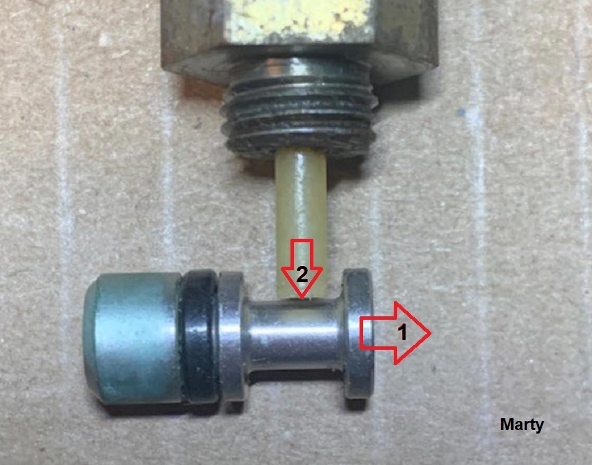
(Only one side of two-part shuttle is shown.)
1. Shuttle
has moved to the low pressure
side, overcoming force of the Spring
on that side, by enough displacement to allow...
2. ...switch
plunger to drop into shuttle minor diameter, and stay there until deliberate
actions are taken to reset it!
Note: With that sharp edge at the major-diameter to minor, it should be clear that in the process of brake bleeding, when the shuttle does move during the bleeding operation, that sharp edge would easily shear away the plunger end, so the plunger MUST be kept clear during the bleeding operation!
Reiterating (with Emphasis!): When bleeding brakes of a Brake Warning Valve equipped car, the Plunger Switch MUST be loosened and withdrawn from the Valve during the operation to prevent damaging it! (No leakage will result!) Switch may be reinstalled when bleeding operation is complete.
Colored Graphic from the Manual, Corrected [Details, details! Reliable and useful as the Factory Manuals are, sometimes they can still use a bit of correction!]:
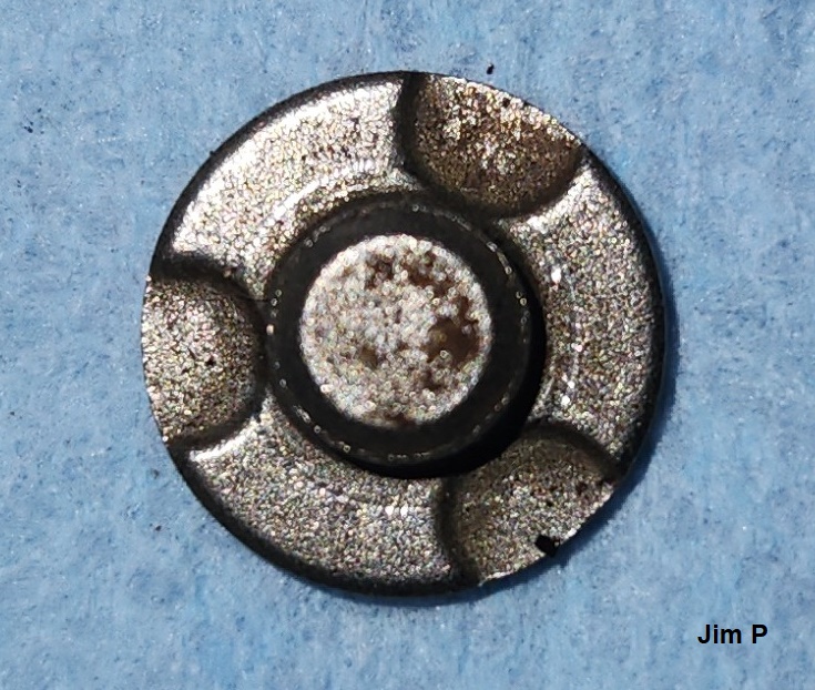
Thrust Washer (also: Hat Washer).
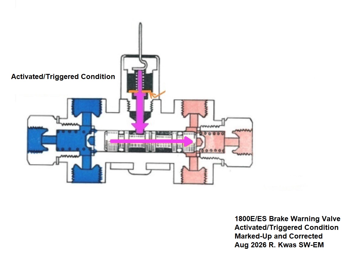
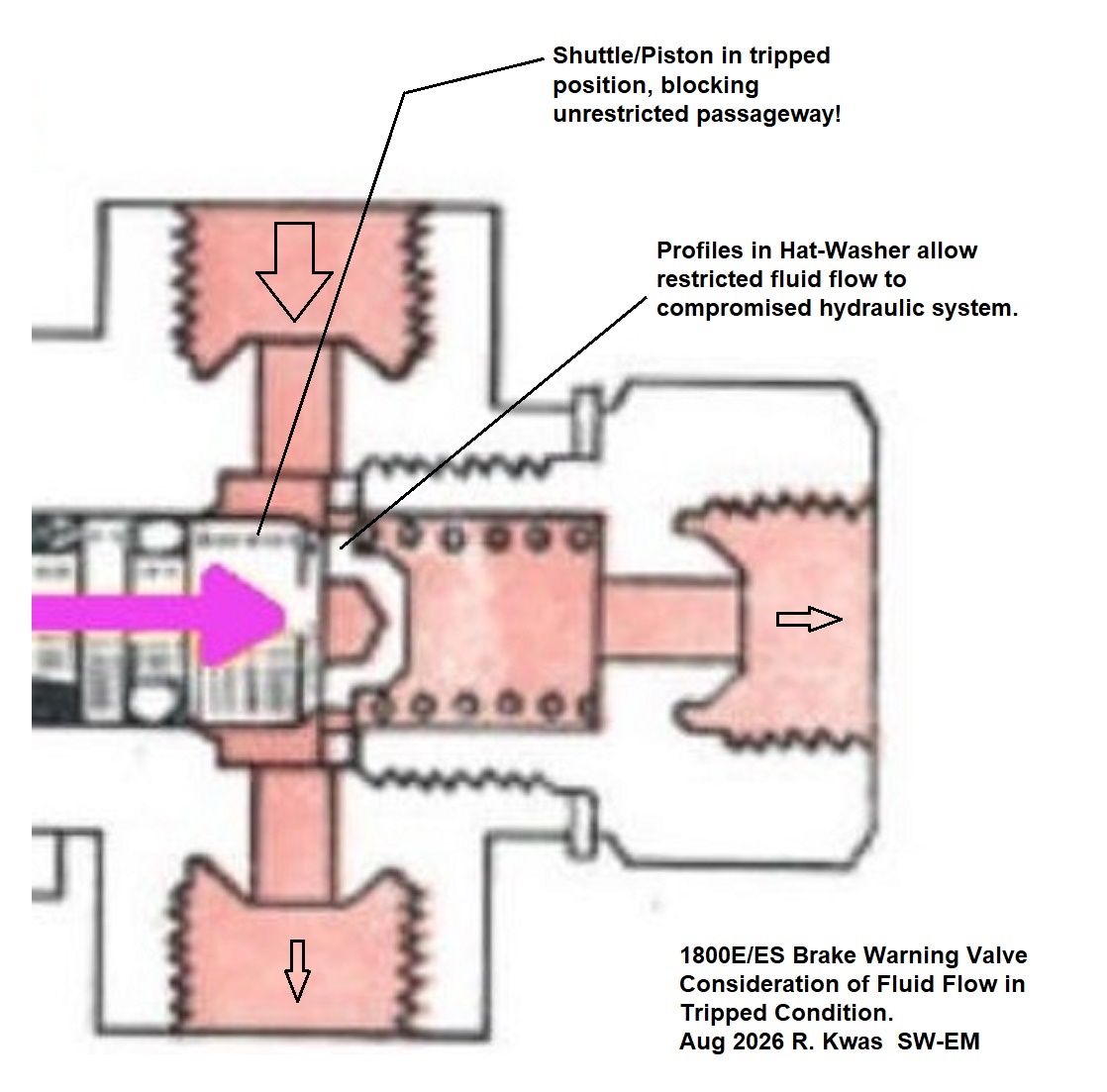
Reduced Flow to the Compromised Hydraulic Circuit?
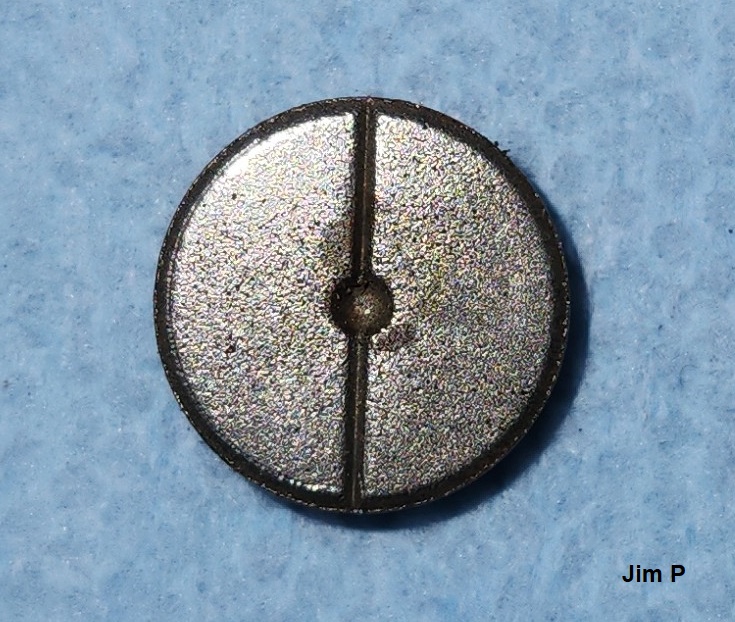
This question came up when an observant Jim Perry noticed that in the tripped condition, the "Hat-Washer" blocks fluid low to that side's system...but on closer observation, it would seem to the author, that a slight passage for fluid would still be open, by way of the slot in the Thrust Washer (11). [To be confirmed!]
Detail of Thrust Washer (thanks to Jim Perry!):
-------------------------------
Links to Referenced and Related SW-EM Articles:
https://www.sw-em.com/OR-ing%20Circuit%20Notes.htm#Examples_of_OR-ing_circuits
https://www.sw-em.com/electical_circuit_interaction.htm#Chassis_Side_Inadvertent_Circuit_Interaction
-------------------------------
Dual Brake Failure Sensing from the Volkswagen World:
The Volvo solution is what I would call a hydraulic solution. According to this graphic, VWs used what I would characterize more as an electrical solution, employing two hydraulically activated SPDT (Single Pole Double Throw) switches and a transistor to control and drive the Brake Warning Indicator. I show the VW solution here because it demonstrates and explains some interesting circuit design and implementation practices...it also incorporates a Bulb-check function which the Volvo implementation does not have (of course being OR-Tied in the Volvo application, we will see the Indicator lit with the Handbrake activated).

VW implementation of a Brake Warning Indicator for dual braking systems.
Unfortunately, I only have the gallery location on thesamba VW site I can
attribute this graphic to:
https://www.thesamba.com/vw/gallery/pix/1824259.jpg ...I expect
it is originally from some VW service manual.
-------------------------------
External material sources are attributed. Otherwise, this article is Copyright © 2026. Ronald Kwas. The terms Volvo, VW, and Smiths or other suppliers, are used for reference only. I have no affiliation with any of these companies other than to try to keep their automotive electrical products working for me, help other enthusiasts do the same, and also present my highly opinionated results of the use of their products here (like giving Lucas all the grief they so richly deserve!). The information presented comes from my own experience and carefully considered opinion, and can be used (or not!), or ridiculed and laughed at, or worshipped, at the readers discretion. As with any recipe, your results may vary, and you are, and will always be, in charge of your own knuckles!
You are welcome to use the information here in good health, and for your own non-commercial purposes, but if you reprint or otherwise republish this article, you must give credit to the author or link back to the SwEm site as the source. If you don’t, you’re just a lazy, scum sucking plagiarist, and the Boston Globe wants you! As always, if you can supply corrections, or additional objective information or experience, I will always consider it, and consider working it into the next revision of this article...along with likely the odd metaphor and probably wise-a** comment.

