Wiring Diagrams and Related
Factory Wiring Diagrams as well as excerpts and mark-ups highlighting certain circuits are collected here. Graphics on this page are in a large format, to be able to see details. Wiring Diagrams are listed here (somewhat) in model-chronological order.
Tip: When checking original wiring in a vintage Volvo vehicle, there is high consistency between published color codes on the Wiring Diagrams and those actually found in the vehicles (not counting of course, wiring work which may have come later...)
"The published color codes are your friend!" Ron [Comments and Clarifications Added!]
Reference (Source of the Numbered Terminals on Wiring Diagrams, German): Source Deutsche Industrie Norm (DIN) specification (DIN 72552) http://www.elektron-bbs.de/verkehr/klemmen.htm
----------------------------------
444 (6V) Wiring Diagram
544 (6V) Wiring Diagram
544 (6V) Wiring
Diagram Mark-up
544 (6V) Wiring
Diagram Excerpts
544/210 (12V) Wiring Diagram
----------------------------

122 Wiring Diagram
122 Wiring Diagram
Mark-up
122 Wiring Diagram
Excerpts
123GT Wiring Diagram
(European Aux Lighting)
123GT Wiring
Diagram (North-American Aux Lighting)
123GT Wiring Diagram
Excerpts
------------------------------

1800 Wiring Diagram
1800 Wiring Diagram
Excerpts
1800 Wiring Diagram
Mark-up
---------------------------------

1800E Wiring Diagrams
1800E Wiring Diagram
Excerpts
Wiring Diagram Excerpt Brake Warning Light
1800ES Wiring Diagrams
1800ES Wiring
Diagram Excerpts
Indicator Brightness Control
------------------------------

140 Wiring Diagrams
Early 140
Wiring Diagram with OE Generator
Late 140
Wiring Diagram with OE Alternator
140 Wiring Diagram
Excerpts
------------------------------
Original Equipment Radio Schematics
-----------------------------------------------
Additional Circuits
Electric Fuel Pump "Crash Safety
or Inertia Switch"
-----------------------------------------------


544 (6V) Wiring Diagram Mark-up:
Brake Light Relay for Trailer Brake Lights:

I have included a Quenching Diode at the relay, to suppress the arcing occurring at the time of contact opening (also during contact bounce while closing). If the original Hydraulic Brake Light Switch is still being used, anything we can do to suppress the arcing, especially with the inductive load of a Relay, will prolong its service life, and is a good idea, given the known failure mode (see: Hydraulic Brake Light Switch Failure Investigation ) ...of course, the best idea is to upgrade to a Pedal Position Sensing Brake Light Switch...
544 (6V) Wiring Diagram Excerpts:
Courtesy Light : Note that there is only one switch, located at the Driver's door. The Passenger's Door does not activate the Courtesy Light!

-------------------------------

Highlighted in Orange is the
Starter Relay, only present in automatic transmission equipped chassis.

Link to Tech Article on Ignition Slave Relay: https://www.sw-em.com/Ignition_Slave_Relay.htm
Link to Fuse your Cigarette Lighter!: http://www.sw-em.com/Fuses,%20Allocation%20and%20Troubleshooting.htm#Fuse_your_Cigarette_Lighter
Directional Indicators:

Link to Tech Article on Blinker Element or nomenclature as seen here "Blinker Mechanism".
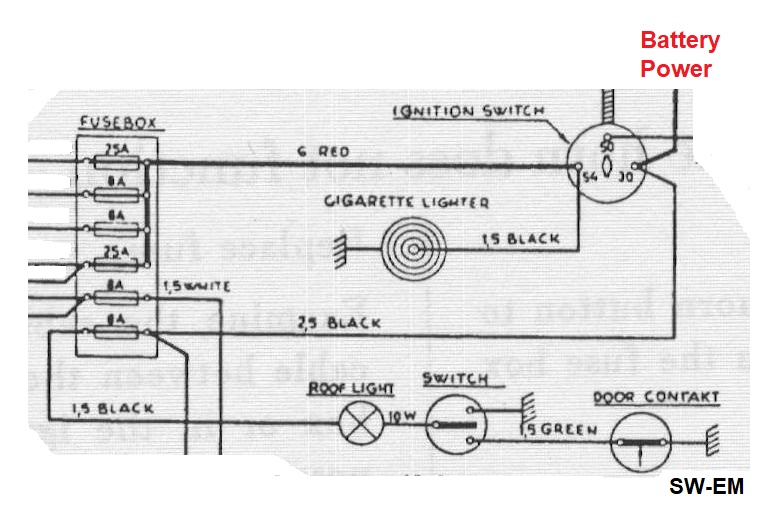
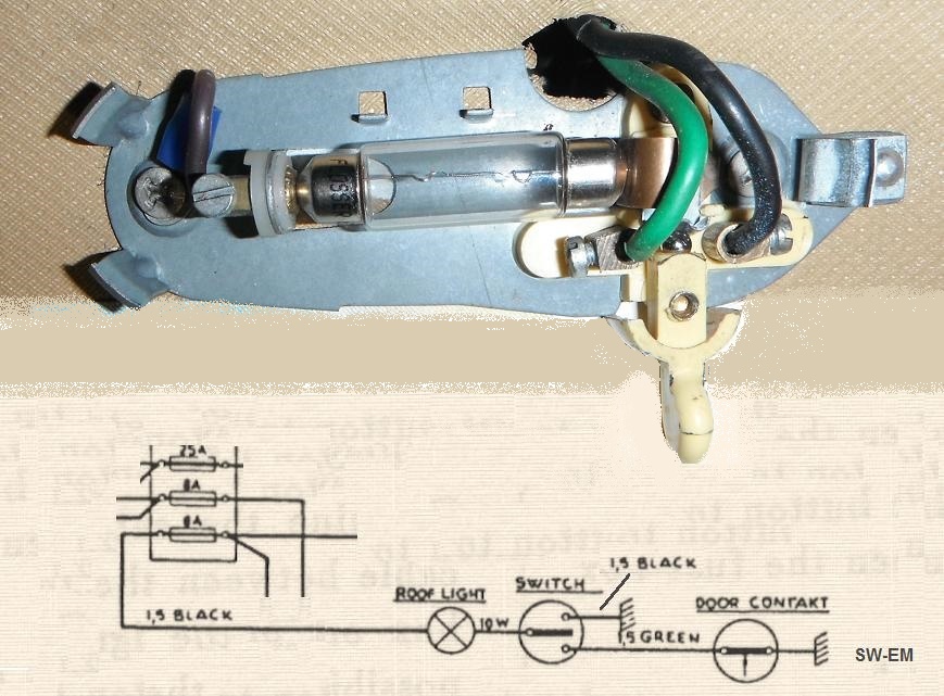
Courtesy ("ROOF-LAMP") and Glove Compartment Lights:

Fuse4 Load circuit. See also:
Courtesy Light Assembly 122/544 Notes
Dashboard PLUS Steering Column Ignition Switch Combination
(found on the last delivered European vehicles).
This unusual condition and wiring is specifically considered in these Notes:
LINK

Link to Lighting https://www.sw-em.com/Headlight_Notes.htm with additional excerpts and mark-ups for lighting changes and improvements.
-------------------------------
123GT Wiring Diagram (European Aux Lighting):

123GT Wiring Diagram (North-American Aux Lighting):

Link to detailed consideration of the European vs North American Lighting
differences:
123GT
Consideration of Lighting Differences
123GT Wiring Diagram Excerpts:
123GT Charging System:

See also:
https://www.sw-em.com/123GT_Charging_System_Notes.htm
-------------------------------

Link to Tech Article:
1800 Light Switch, Wiper Switch, Fan Switch Drawing Corrections

Note: Unfused Ignition Power supplies Electronic Ignition Module [This is
a considered risk/reliability trade-off!]
Links considering mark-ups:
Switch Internal Detail Corrections:
1800 Light Switch, Wiper Switch, Fan Switch Drawing Corrections
Addition of 20A Fuse to OD Control Circuit:
https://www.sw-em.com/OD_Retrofitting.htm#OD_Solenoid_Notes
Ignition Slave Relay:
https://www.sw-em.com/Ignition_Slave_Relay.htm
Momentary Start Switch:
https://www.sw-em.com/swemkits.htm#Start_Switch_1800
Fuse 3 Current Rating Change:
https://www.sw-em.com/tech_bulletin_4.htm
Control of Headlights with Bistable Relay on an 1800:

Link to:
Control of Headlights with
Bistable Relay on an 1800
Directional Indicators:

Link to Tech Article on Blinker Element or nomenclature as seen here "Blinkdon för Korvisare".
Courtesy Light:
There are model variations! See: https://www.sw-em.com/Courtesy_Light_1800_Notes.htm

-------------------------------
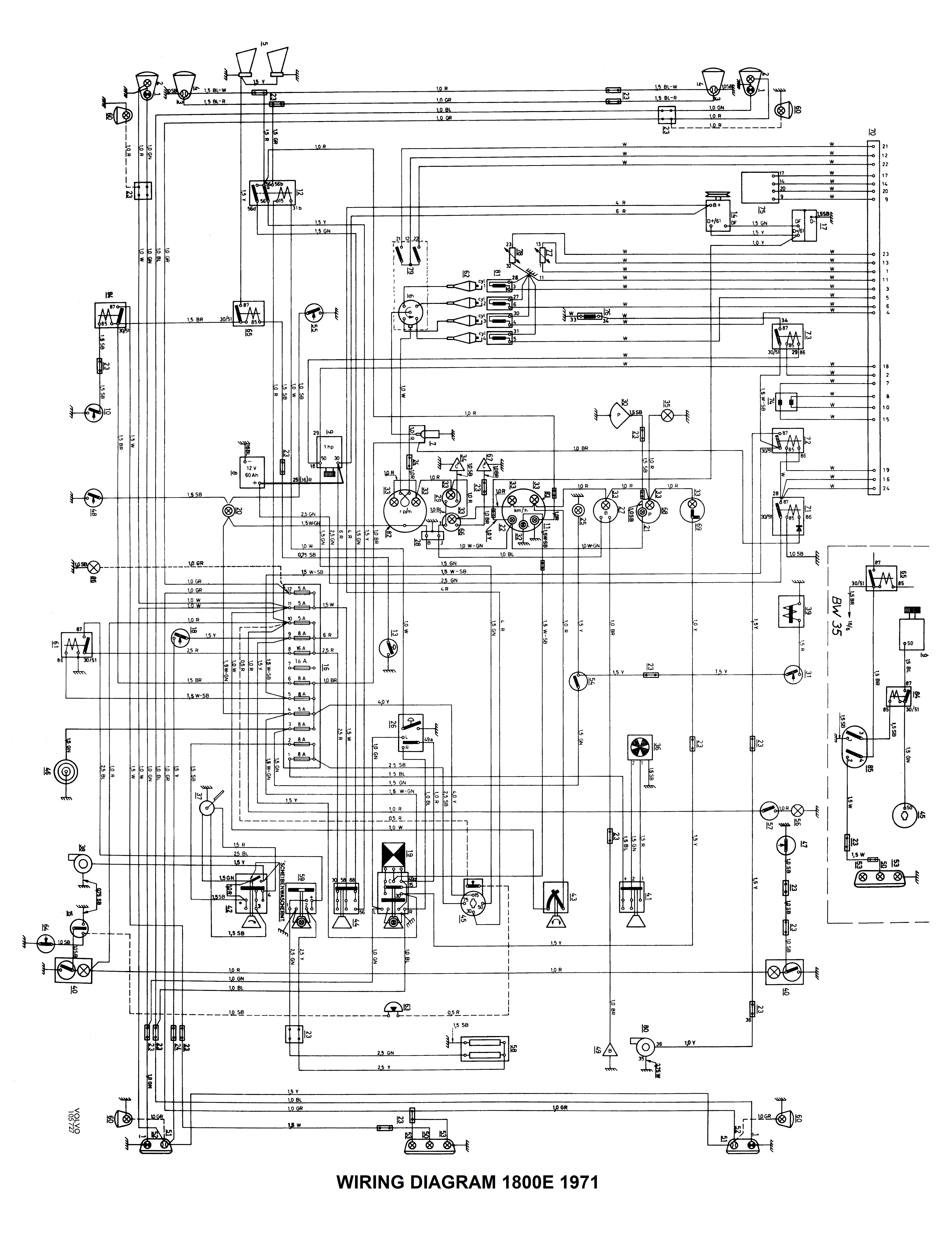
1800E Wiring Diagrams (Pull Switches on Dashboard!):

For Fuel Injection Wiring Diagrams, link to: http://www.sw-em.com/bosch_d-jetronic_injection.htm#71_1800E_Fuel_Injection_Wiring_Diagram
Bosch D-Jetronic Fuel Injection
1800E Wiring Diagram Excerpts:
Directional Indicators:

Link to Tech Article on Blinker Element.

Relay (61) which supplies power to the Rear Defroster is powered whenever
Ignition is ON (note the high current 2.5mm2 path of heavy gauge
wire). This means Ignition Switch is not burdened with this high
current...good design practice on the part of Volvo! See also:
Ignition Slave Relay
Charging System:

Instrumentation Power, Voltage Stabilizer, Oil, Water Temp and Fuel Gauges:

Variable Instrument Lighting:


Brake Warning Indicator(20) is
OR-Tied and can be activated by a conductive path to
chassis by a switch at the Handbrake(48) OR by the Brake Warning Switch(55) located on
the Six Branch Union on the two braking systems. See also:
Link to function of the Brake Warning Switch
Tachometer:

-------------------------------
1800ES Wiring Diagrams (Rocker Switches on Dashboard!):

Notice minor correction at Item 23 "Connector" for Courtesy Lighting. See
also below!

A minor correction to the factory Wiring Diagram is necessary, where "Item 23, connector" on factory WD does not show an internal through-connection:

Excerpt of my response on
![]() questioning the
manner Item 23 (Connector) is shown in factory WD.
questioning the
manner Item 23 (Connector) is shown in factory WD.
"The Item 23 "Connector" shown near Interior Lamp [Item 40] does not have an internal connection between the two terminals...this is incorrect (if it was correct like that, it would mean ONLY Pass. side door would control the Key in Ign Buzzer!), which would be pretty funny [and useless, practically speaking!]...with a connection between the two ends of the connector, EITHER Door open will cause Buzzer to sound."
[This applies to ALL occurrences of these "Item 23, Connectors" on factory WDs, without exceptions].
1800ES Wiring Diagram Excerpts:
Directional Indicators / Emergency Flashers:

The
4 contact Blinker Element is fitted when pushbutton Emerg Flasher Switch was
fitted.
Link to Tech Article on Blinker Element or nomenclature as seen here "Flasher Unit".
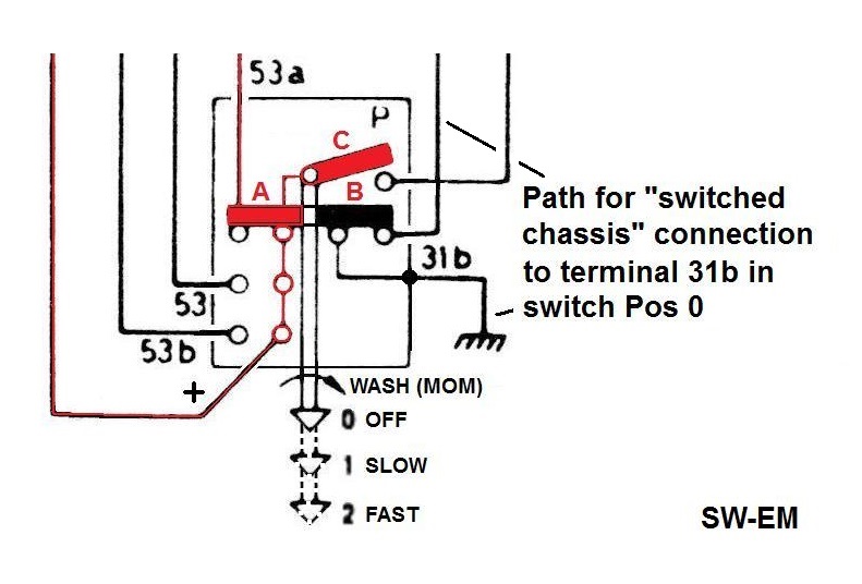
Wiper Wiring:

Indicator Brightness Control (Hi/Lo Beam and OD Indicators only. This does not apply to variable lighting of other instrumentation!):

Hey!...that's not a Wiring Diagram!

For Fuel Injection Wiring Diagrams, link to: http://www.sw-em.com/bosch_d-jetronic_injection.htm#D-Jet_in_73_1800ES
-------------------------------
Early 140 Wiring Diagram with OE Generator fitted:

Late 140 Wiring Diagram with OE Alternator:

Wiper Switch Excerpt for Dynamic Braking:
Voltage Stabilizer (5.1V) and associated (See also: https://www.sw-em.com/voltage_stabilizer.htm#140_VStab_Info ):

-------------------------------
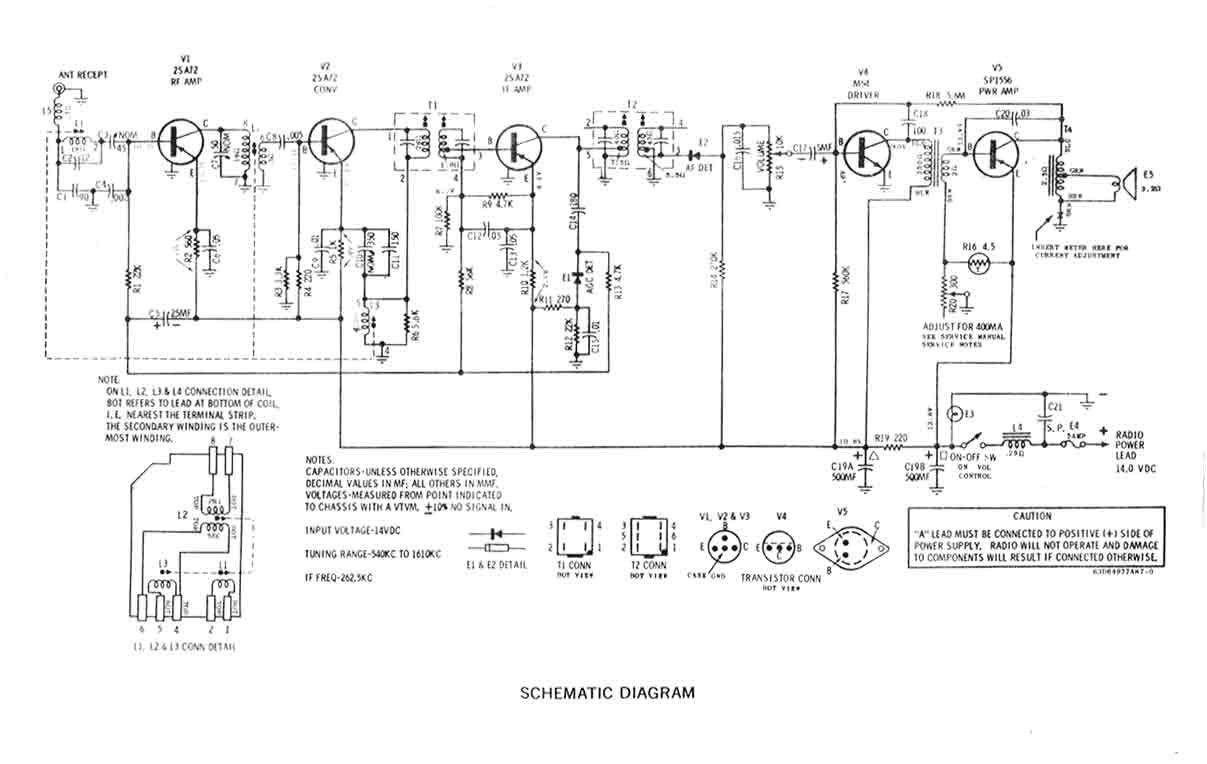
Original Equipment Radio Schematics:
Bendix AM:

Motorola AM:
-----------------------------------------------
Electric Fuel Pump "Crash Safety or Inertia Switch":

An "Crash Safety or Inertia Switch" provides the safety function that FuPu power
is interrupted after crash "Gs" are experienced. See also:
Fuel Delivery Considerations
-----------------------------------------------
External material is attributed. Otherwise, this page is Copyright © 2021, Ronald Kwas. The term Volvo is used here for reference only. I have no affiliation with this company, other than to try to keep its vintage products working for me, and to encourage and help other enthusiasts do the same. The results presented here are from my own experience, and can be used (or not, and used strictly for your amusement around the watercooler!) at your discretion. As with any recipe, your results may vary! As always, if you can supply corrections, or additional objective information or experience, I will consider it, and consider working it into the next revision of this article...along with likely the odd metaphor and possibly wise-a** comment.
You are welcome to use the information here in good health, and for your own non-commercial purposes, but if you reprint or otherwise republish this article, you must give credit to the author or link back to the SwEm site as the source. If you don’t, you’re just a lazy, scum sucking plagiarist...the Boston Globe wants you!