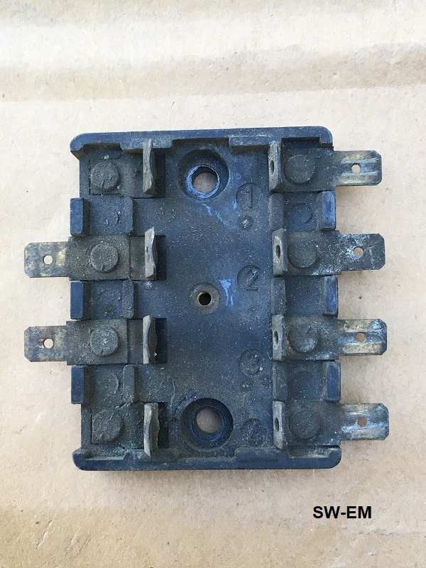
123GT FB2 core, as received...frontview...not so pretty, but all there, so a good candidate for a rework!
123GT FuseBlock Rework
Feb 2018 R. Kwas Revisions on-going
[Additional Comments]
---------------------------
Intermediate Steps
Fuse Allocation Tab
(FB2)
Reference Information:
Fuseblock Core Notes
---------------------------
Key steps of the rework of a FuseBlock2 of the Volvo 123GT are shown (these are substantially the same as steps for rework of FB1[which is identical to FB fitted in a 122, and 12V544], but shown here to also highlight some of the unique features and differences in the FB2).
Not shown, are specially developed tools and techniques...[I can't give away all my secrets!]
The observant reader may notice the words careful and carefully used here a number of times...this is not coincidental!
---------------------------
123GT FB2 core, as received...frontview...not so pretty, but all there, so a
good candidate for a rework!
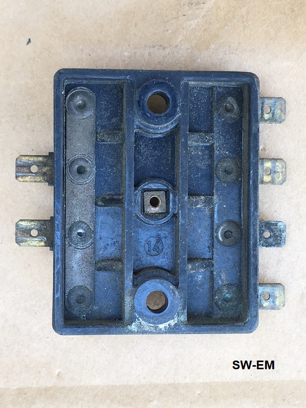
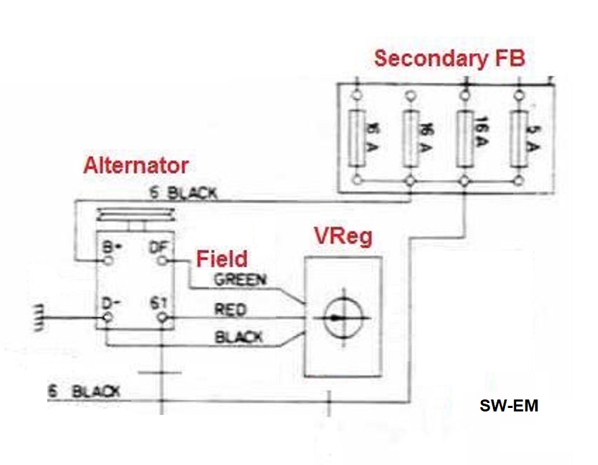
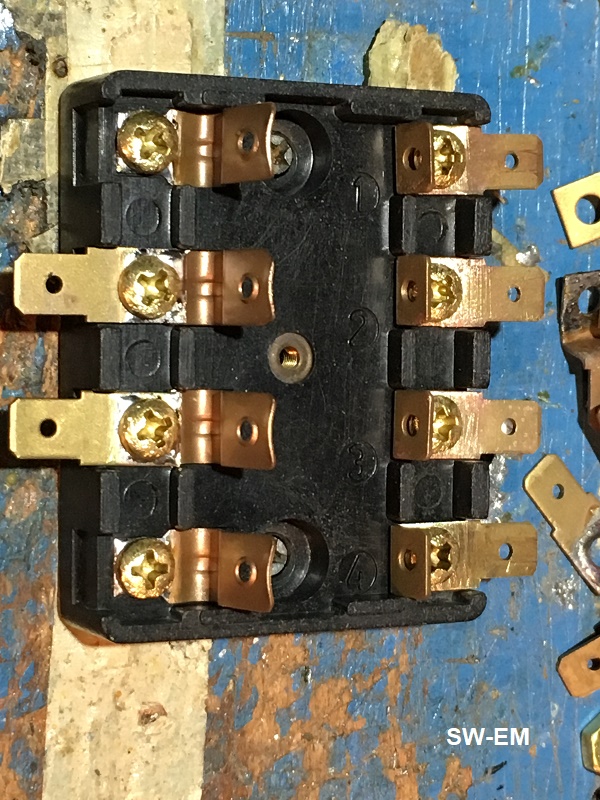
Rearview, with conductive commoning strap (unique to FB2 of the 123GT as seen
also in the wiring diagram excerpt), which
ties all source sides together, clearly evident on left. (See also:
123GT FuseBlock 2 ). Also evident are
dirt and corrosion products of varying colors.
.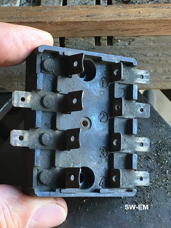
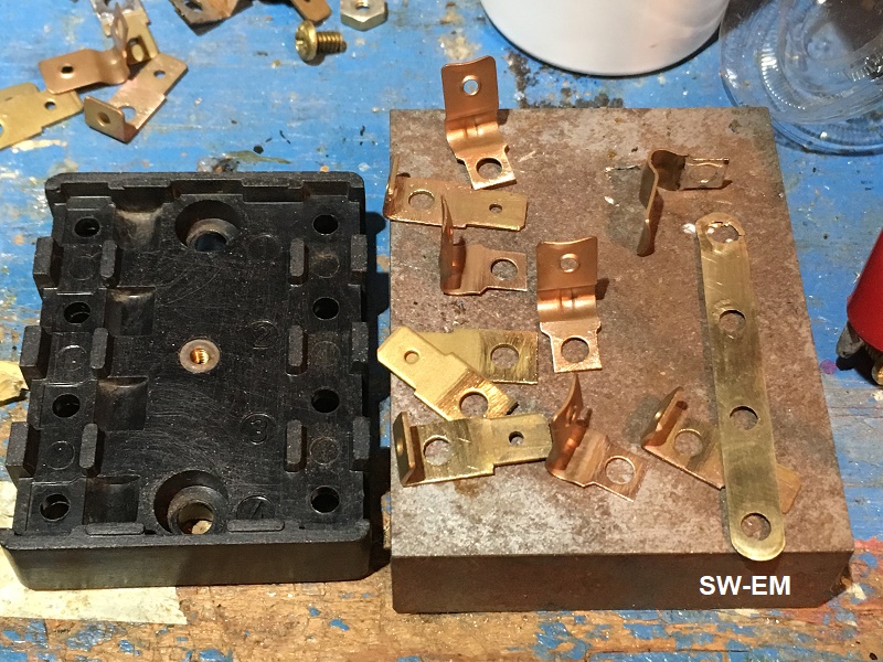
FB at the drillpress, ready for separating terminals from base.
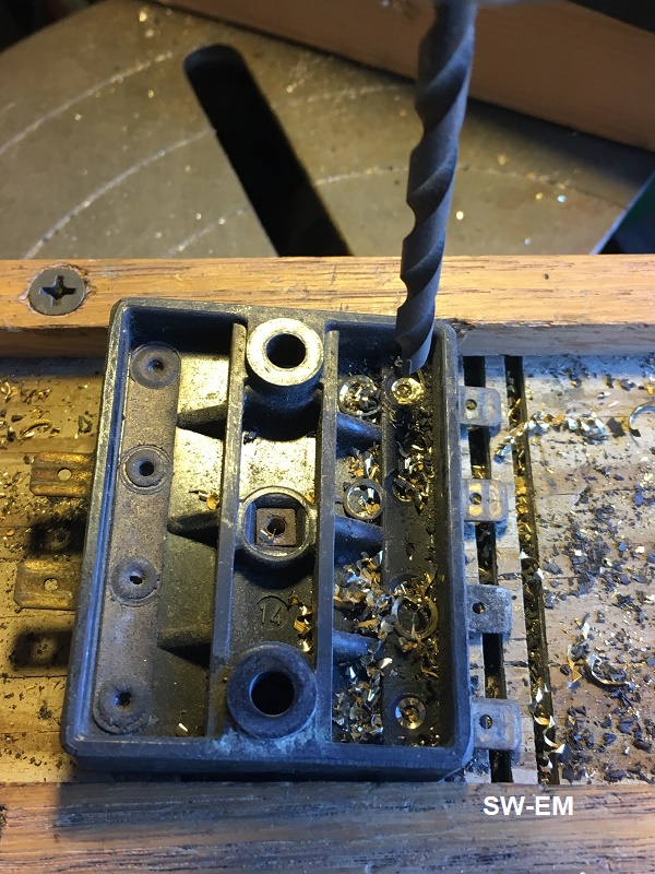
All rivets are carefully drilled out of the brittle Bakelite housing.
...too much force, and Bakelite fractures!
FB is supported just right by a specially constructed wooden fixture.
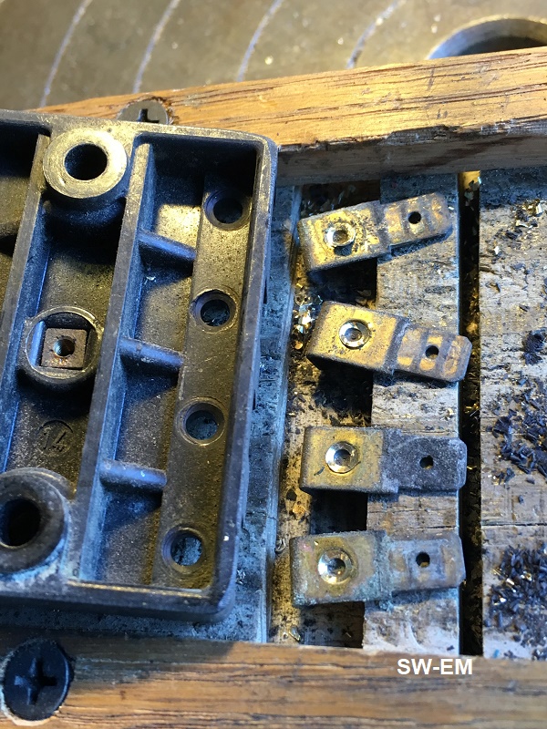
Brass terminals are carefully separated from the base. Here, some are
laid out for inspection...corrosion has worked it's way between all, especially
the lower terminal.
If it is not clear, from the pictures here, why these FBs require rework, here is link to discussion of the electrical reasons for which it is necessary: Gas-Tight-Joint
Also, and particularly applicable to the 123GT FB2 because of the Alternator based Charging System, if the incoming power connection (output of the Alternator) ever were to become electrically open due to terminal corrosion, the system could be subjected to a load dump voltage surge, possibly resulting in damage to voltage sensitive components on the power buss (in the Alternator, or Radio, etc.). This is addressed and explained further here: https://www.sw-em.com/123GT_Reliability_Weakness_and_Simple_Improvement.htm#Supporting_Info_Charging_Sys_and_Battery
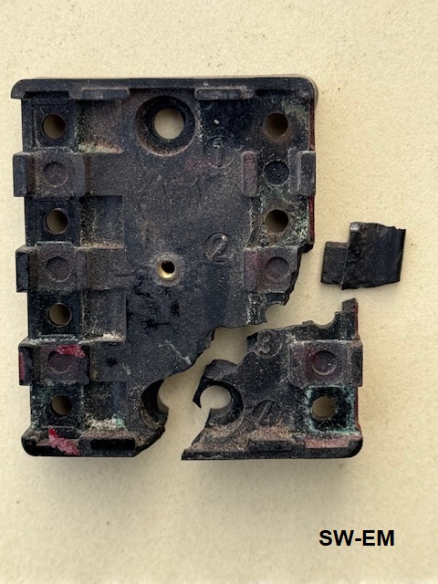
Even when well supported, and drill is advanced gently, and judgment and "feeling" are used, the brittle Bakelite can still fracture...
Liberated terminals are strung onto a wire, and blasted clean with fine media.
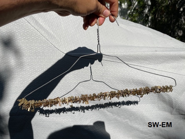
Cleaned Terminals are abraded to further clean solder surfaces, removing blasting media which gets embedded in the surface, and tinned using 60/40 electronic solder.
Note: The 60 refers to the percentage of lead content of the solder!
 ...but
there is no need to over-react!
...but
there is no need to over-react!
See: https://www.sw-em.com/Wiring%20Notes.htm#Lead_Poisoning...Hogwash
Bakelite base is carefully cleaned well!
Cleaned components laid out in preparation for reassembly. Terminals are
clean, abraded in the area to be soldered, and not yet tinned. Clearly apparent is the long brass commoning strap
unique to the GT FB.
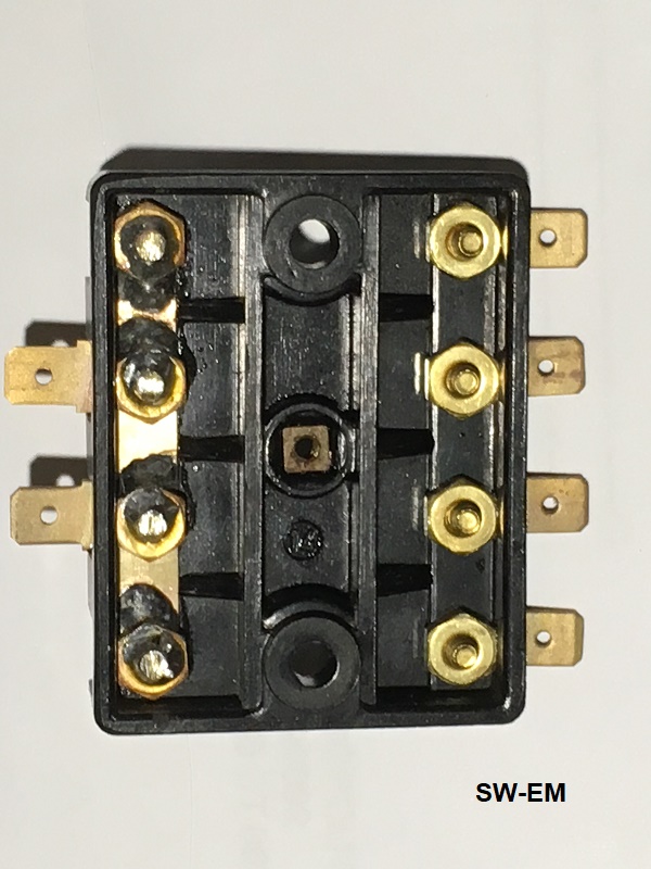
Reassembled FB, before reflowing
of the terminal hardware. Brass Hardware is evident.
Completed FB. All terminals have been reflowed, simultaneous torquing, and
solder added to fill the Phillips heads. Frontview.
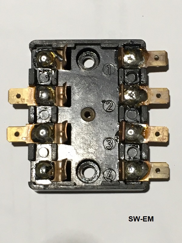
Rearview, showing additional solder from power input terminal screws to
commoning strap for absolute minimum in-line resistance, and optimum monolithic
gas-tight connection of all terminals. Voltage drops occurring here
will be at their absolute minimum, and for a very long time!
because of the Gas-Tight-Joints!
Additional Steps:
All exposed brass is coated in Deoxit D5 terminal Treatment.
Central threaded insert gets a dab of ACZP.
FB Cover is replaced, if customer included it (not really necessary!), with the returned FB.
Reworked FB is packaged, along with additional ACZP for optimum fuse installation, for return to customer.
-------------------------------------
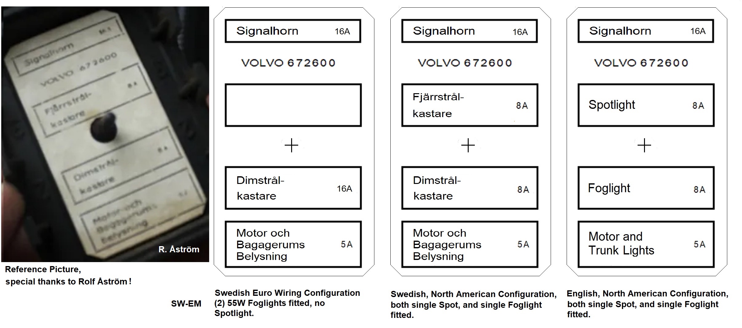
Once the FB2 is looking its best and functioning better (than new!), you might be interested in adding this little detail. It's the Allocation Tab PN 672600, just inside the cover (similar to what the FB1 has!).
If the Fuseblock Cover of your 123GT is missing the cute little insert which identifies which fuse supplies which load, here is a graphic with which you can make a reproduction of the little chart. Note that both Euro and US additional Lighting versions are shown (See Reference Info!)...select and make up the one for your language of your preference, appropriate for vehicle configuration! Note also, that Fuse values vary with installed equipment!
Copy this file, import it into a document program like MS Word, enable the
ruler function so that the surrounding octagon can be sized to 1 1/8" X 2
1/8" or 29mm X 54mm and print, preferably on the heaviest ivory card stock your
printer can handle (and a preferably laser and not ink-jet), cut out on the
octagon, punch a 1/8" hole in the center, treat the paper with a spray-on clear
lacquer, and place on the threads of the FB Coverscrew.
Reference picture is from https://vintageswedishcars.com/ , Rolf Ĺström's page with the most comprehensive 123GT Spotters Guide I've seen! Special thanks also for his help with the Swedish!
Viola...just like new...and BTW, these are of course included in the reworked
FB2s offered under the
SW-EM Kits page!
[Plug!]
-------------------------------------
Link to: Fuseblock Core Notes
Note: Euro and US Wiring Diagrams have differences in Lighting wiring, but not in the FB1 or FB2 areas!
123GT Wiring Diagram (Euro version): https://www.sw-em.com/123GT-Wiring-Diagram_Euro.jpg
123GT Wiring Diagram (US version): https://www.sw-em.com/123GT-Wiring-Diagram_US.jpg
-------------------------------------
Links:
Read about FuseBlock1 long-term weaknesses in 122, 123GT, also 12V544 vehicles, symptoms, and corrections, here: https://www.sw-em.com/gastight.htm
If the reader is not in a position to perform the steps shown here, they could simply buy a reworked FB! See: https://www.sw-em.com/swemkits.htm#restored%20fuseblock
-------------------------------------
This information is Copyright © 2018-2024. Ronald Kwas. The term Volvo is used for reference only. I have no affiliation with this company, other than to try to keep its products working for me, help other enthusiasts do the same, and also present my highly opinionated results of the use of their products here. The information presented comes from my own experience and carefully considered opinion, and can be used (or not!), or ridiculed and laughed at around the watercooler, or worshipped, at the readers discretion. As with any recipe, your results may vary, and you are, and will always be, in charge of your own knuckles and future!
You are welcome to use the information here in good health, and for your own non-commercial purposes, but if you reprint or otherwise republish this article, you must give credit to the author or link back to the SwEm site as the source. If you don’t, you’re just a lazy, scum sucking plagiarist, and the Boston Globe wants you! As always, if you can supply corrections, or additional objective information or experience, I will always consider it, and consider working it into the next revision of this article...along with likely the odd metaphor and probably wise-a** comment.
