The Integral Lifting Pin of the SU HS6 Carb, used for mixture checking (at Idle).
SU Carb Lifting Pin for Mixture Checking
Jan 2026 R. Kwas [Comments added]
-------------------------------
Link to full Tech Article on SU Carbs
Some of the material in the article may be repeated here: SU Jet Bearing and Supply Tube Notes
Analysis of The Lifting Pin
Mixture Test
Review of
Normal Dashpot and Action
Dashpot Action
during the Lifting Pin Mixture Test
Jet Height Position
Study
Dashpot and RPM Action with Lifting Pin
Reference Information
SU Jet
Assembly exploded Diagram
Initial
Mixture Setting and Adjustment
Properly installed Metering Needle
SU KD
and ZH Metering Needle Comparison
That
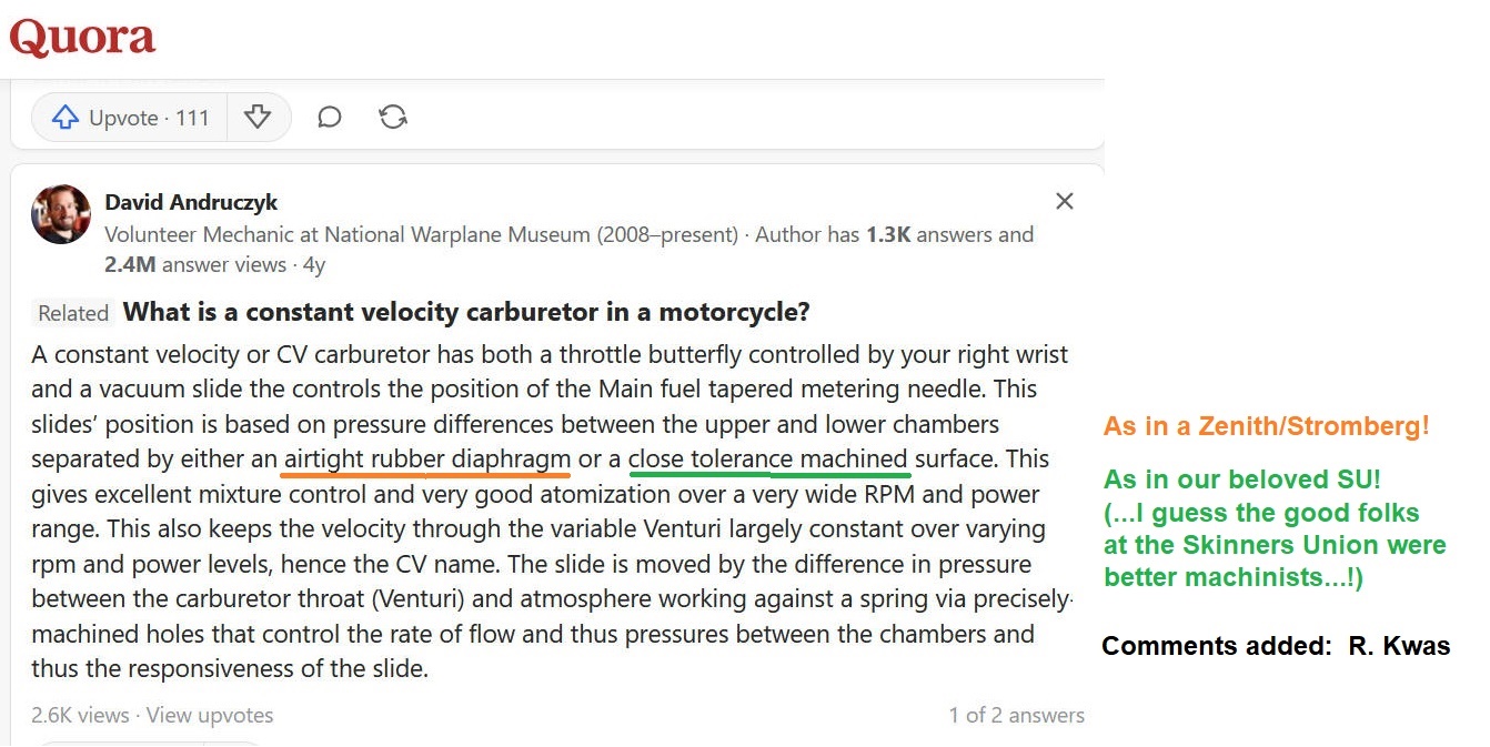
"Variable-Venturi/Constant Velocity" thing!
-------------------------------
The Lifting Pin on the Fuel Bowl side of SU HS6 carbs is a built-in-test provision, conveniently included by the manufacturer of these carburetors, and used for checking the Idle fuel-air mixture at tune-up time. These notes are intended to understand and explain its function and use.
I am hereby revisiting this subject... I've said before, I never really got the response shown in the manual on my cars (quite likely because of worn Throttle Shafts) so I rarely use them, preferring the feedback and feel of Throttle-response of a Road-test on which to decide if I thought the mixture was performing well, but the subject came up again, so here are my notes and observations.
The Integral Lifting Pin
of the SU HS6 Carb, used for mixture checking (at Idle).
My response to a question about an "un-smooth" Lifting Pin, and alternately using a screwdriver to lift the Dashpot for mixture checking: https://www.swedespeed.com/threads/question-on-tuning-the-su-carbs.701155/#post-8432315
"Using a small screwdriver
[instead of the Lifting Pin, or as seen
below, a strategically sized hexwrench] to
lift the Dashpots is fine, just be sure to lift them equally, and as much as the
Lifting Pin does when used (I would bet that before SU built them into the carb
body, that, or by inserting a rod of a given diameter between Dashpot and
Venturi bridge is exactly how they would lift them...(then they said: "Hey, it
would be handy, and easy to build a lifting provision into the body of the carb...")
Lifting Pins spend 99.9999% of their existence just sitting there waiting and
hoping to be used in service, so they can accumulate dust, debris, and even
rust, which can explain their unsmoothness...a blast with carb cleaner, and drop
of oil on them, and their Spring from above, the next time Domes are off, will
clean, lube and smoothen their action...but I have always found using them to
check for and adjust mixture by checking for idle smoothness is pretty
touchy...and it's quite dependent on the Idle RPMs you start with (down low,
it's difficult to keep it from getting rough and lumpy anyway!)... I rarely got
it to work as it was shown in the service manual, preferring to make the final
adjustments to mixture settings based on throttle response during a road-test,
where it really matters."
Additionally,when asked about the "...procedure a lift and hold or a lift and release?":
[Edited for clarity] "The Lifting Pin does just
that...lifts the Dashpot a certain amount
directly and mechanically (above the Venturi)...it has no
latch, so you must "lift and hold" while taking note of the idle RPMs...the
Lifting Pin does
have a Spring to return the Pin mechanically to its rest position, allowing the
Dashpot to also drop
back down when you release...when released, the Dashpot lift is strictly determined
by the amount of Intake manifold vacuum the Throttle opening allows into the
volume above the Dashpot to lift it
[determined by Idle RPM adjustment].
Vacuum leaks will play havok with all of those things...find and eliminate those
first! "
--------
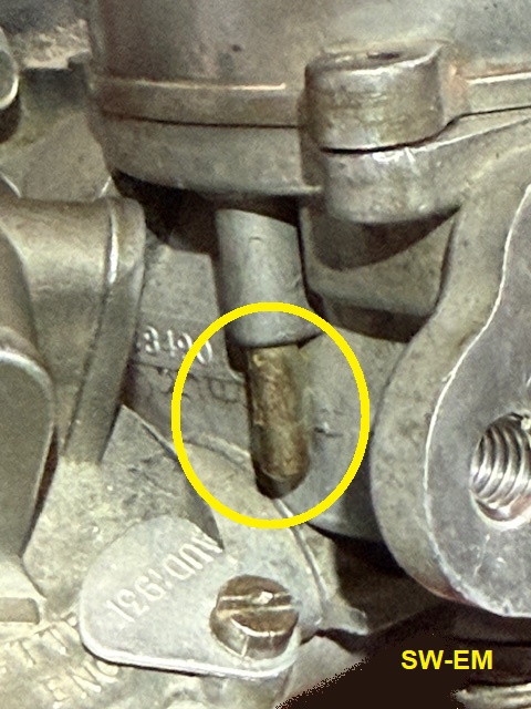
A closer look, with Dome removed, at the Lifting Pin, activated by lifting approximately 3/8" from below. A circlip secures a Washer and the Return Spring. The mechanical assembly will benefit from a drop of almost any kind of oil every time the odometer registers another 50,000 miles!
Just how much does the Lifting Pin lift the Dashpot? By my careful observation and measurement, the Lifting Pin imparts 5/32" or 0.156" (3.97mm, calculated) of lift to the Dashpot, over the Venturi.
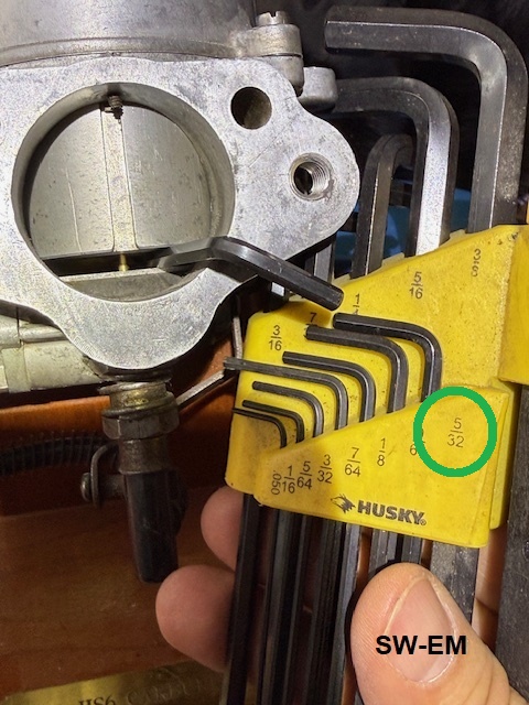
A practical test in which hexwrenches were tested for fit into the clearance above the Venturi when the LP is activated, shows that a 5/32" just fits, meaning that such a wrench can be used continuously, freeing up BOTH the mechanic's hands! The 90ş bend in the wrench keeps it from falling into the carb (Throttle is closed during test anyway, so it won't get sucked or fall in, unless you really try to make this happen!).
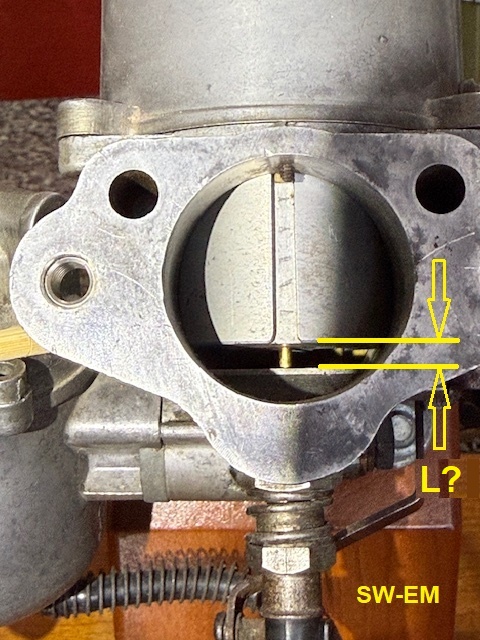
When lifted, the LP raises the Dashpot 5/32"
above the Venturi: L = 5/32"
or 4mm.
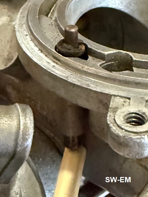
Picture of Lifting Pin activated with Dome removed to allow seeing the resulting lift transferred to the Dashpot: With my finger lifting the pin, the same as a 5/32" hexwrench. A finger gets tired after a few seconds, the hexwrench doesn't mind doing prolonged duty!
Note: Since it rests and its lift starts below the Dashpot resting level, the Lifting Pin will be pushing up about a total of 3/8", but only a 5/32" slot will remain between Dashpot and Venturi.
Gauging what hexwrench can be used to lift the Dashpot, on a Carb with Dome
removed.
A retrofitted threaded Air-Filter securing hole is also evident on this carb. This is a retrofit covered in another Tech Article: LINK
Analysis of The Lifting Pin Mixture Test:
The point of the LPMT is to raise the Dashpot a fixed and very specific amount, and also expose a specific Diameter of the Metering Needle, based on the Jet height setting!
Review of Normal Dashpot Action of our beloved SU Carb: Normally, we [the Throttle Operator aka: Driver] are only indirectly in control of he Dashpot. It rises in response to how much Intake Manifold vacuum the Throttle Operator allows into the vacuum chamber above the Dashpot...which is (intentionally!) a roundabout way of saying how the Driver commands how much power he wants from the engine with the Throttle. As the Dashpot then rises in response, it exposes a larger cross-sectional path for more air to pass the Venturi. It this way, the speed at which the air rushes by the Venturi remains unchanged (there's that "Variable-Venturi/Constant Velocity" thing!) and simultaneously exposes a skinnier part of the Metering Needle to allow more fuel for that additional air. Since the velocity of the air hasn't changed, the diameter of the MN is the one variable which determines the Air/Fuel ratio (its a mechanical predecessor to an electronic look-up table!)...quite brilliant really!! The other variable here would be the fine height adjustment of the Jet, from the initial "two turns down" starting position, and that is what is supposed to be adjusted here based on this test....
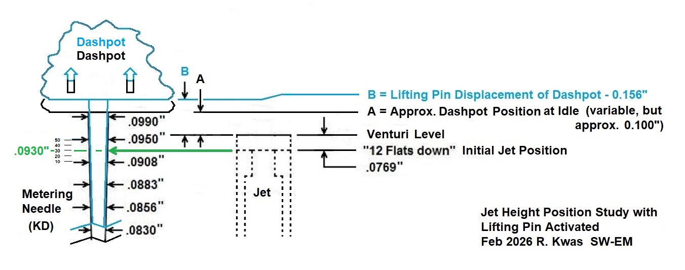
Dashpot Action during the Lifting Pin Mixture Test: During the LPMT in contrast, there is no Driver input at the Throttle...it remains unchanged from its setting, having been previously set to the Idle RPMs. The mechanic directly lifts the Dashpot a certain amount (which I have determined through careful research and measurement to be 5/32"/0.156"/4mm. This bypasses the normal, automatic/indirect manner in which it is lifted by vacuum, and manually raises the Dashpot at a known height, and in turn exposes a specific metering diameter of the Metering Needle. Presuming we start our test from the "12 Flats Down" initial mixture position, where the Jet is 0.0769" below the Venturi, and add the 0.156" LP caused rise of the Dashpot, this carb is now operating at some condition determined by the fine engineers at SU, to be the LPMT Point.
The numbers shown here are essentially correct, to my closest estimation, and include the important additional A dimension which would also have an affect on things...and that is: The Dashpot opening height at Idle...which is not a fixed value, but which varies with adjustment (I have entered an estimated value of 0.100" here). I will need to study this further before I can make profound and insightful statements...
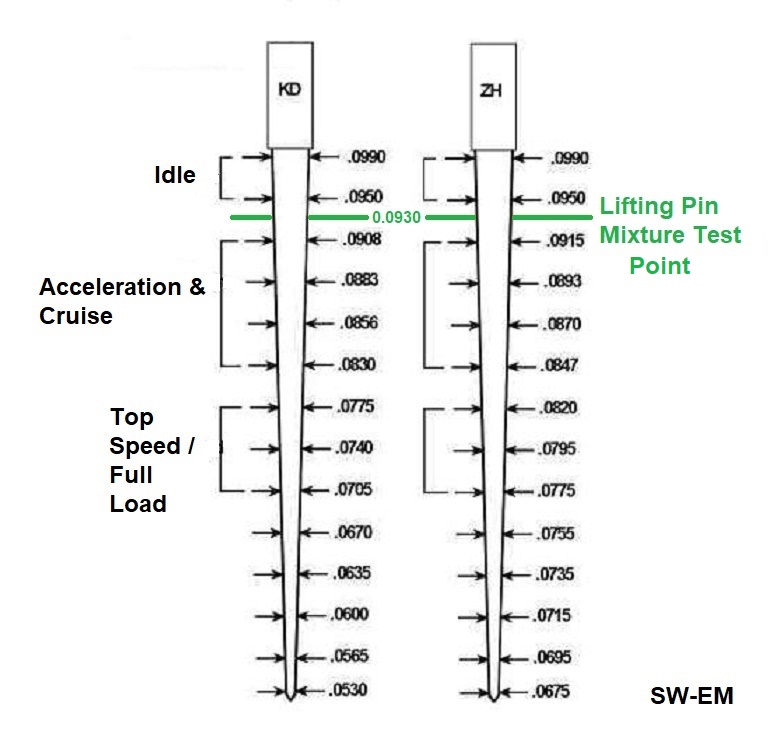
What I can take from the following study is that
at idle, the MN diameter is
0.0930", and when the Lifting Pin is activated, it decreases to approximately
0.0910", a decrease of 0.0020", therefore a bit more fuel will be added
to the increased cross-sectional area of the Venturi. It is my guess that
this is a specific and intentional operating point that the developers at SU
selected, at which to check the engine operation...I can honestly not give any
more profound or insightful statements to the Lifting Pin Mixture Test Point
than that...but I have checked the
Metering Needle charts and The KD, and ZH See:
SU KD and ZH Metering Needle
Comparison and they are quite close at 1 1/2 stations down on the
MN, but they all are quite close in OD, so close to the MN shoulder, as one would
expect.
Jet and Metering Needle Position
Study
Dimensional Study
...so I will leave the reader with the following (somewhat less profound and insightful observation than I was hoping I could make): The amount of manual lift of the Dashpot with the Lifting Pin, has been carefully considered and arrived at by engineers at SU, likely after hours of development time on an instrumented engine with exhaust analyzers. I will try to further analyze and reverse-engineer their work for the purpose of understanding and explaining it better, but in the meantime, I'll just accept it!
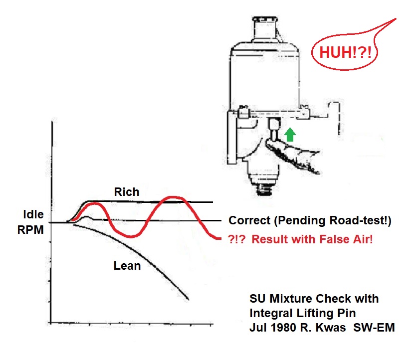
Dashpot and RPM Action with Lifting Pin:
This is the diagram shown in the manuals. I have added what you can expect if your intake system is ingesting False Air: An unrepeatable and inconsistent result! In the end, if you believe you have a correct mixture, the final test is always the Throttle Response during a road-test!
Instructions for use of the Lifting Pin. Extract from: Tuning SU Carburetters by Speedsport Motobooks ISBN 85113-072-0
5 (a) Check for correct mixture by gently pushing the lifting pin of the front carburetter up by 1/32" after the free movement has been taken up. The graph illustrates the possible effect on engine RPM. [...and just how is a guy supposed to accurately measure and lift that 1/32"?? That's why I came up with the method of lifting it to the Stop those 5/32"!]
(b) Repeat the operation on the other carburetter and after adjustment, recheck since they are all interdependent.
Checking SU idle mixture with the Lifting Pin...
To adjust the mixture based on these test results, loosen/lower the Jet/Mixture) Adjustment Nut to richen, or tighten/raise the JAN to lean. Make adjustments one flat of the JAN at a time, the retest.
Note: The Jet Locking Nut does not need to be loosened to allow a height adjustment on the Jet. Function of the JLN is to "lock" the Jet position after centering (See: Centering the Jet). The J/MAN is effectively locked from turning by the Adjusting Nut Spring, which preloads against the MAN thus locking the adjustment. See also SU Jet Assembly exploded Diagram below!
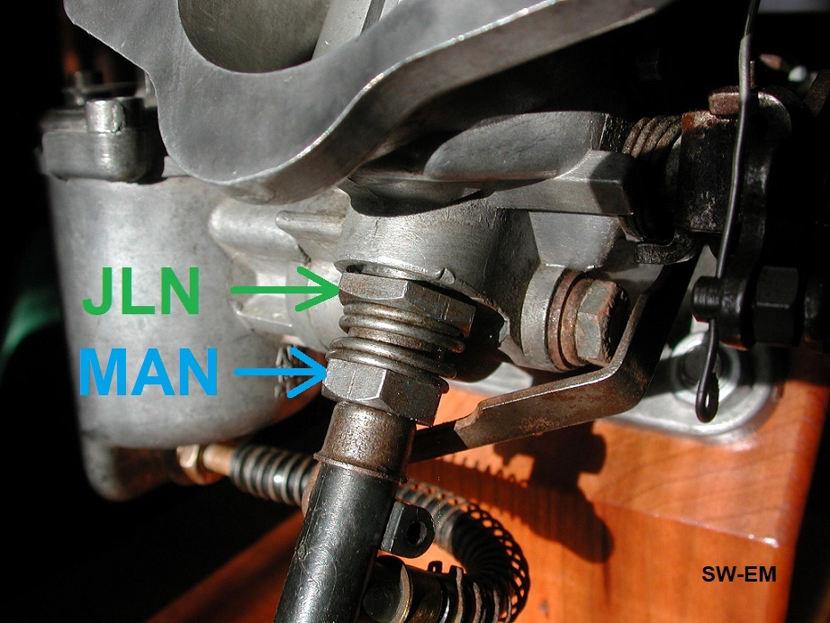
SU HS6 showing Jet
Locking Nut (also Jet Holding Screw) (11/16", 18mm), and Mixture Adjustment Nut
(9/16", 15mm).
-------------------------------
Finally: This article has been reviewed by my SU expert and resource: Tom Bryant, who doesn't like the Lifting Pin much in the first place...he states in his excellent article on tuning SUs [...worth a read!]: "...those lift pins under the pistons; they’re useless.". Source: https://thosbryant.wordpress.com/2015/10/04/su-carburetor-tuning/ ...so I expect you won't be seeing him use them when he does a tune-up, even with his beautifully rebuilt carbs, which are most definitely NOT sucking any False Air anymore, so might even have half a chance of them working like shown in the graphic...!
Tom's Bryant's Profound and Insightful Comments (included here with his blessing, my original comments in Turquoise):
"Ron,
I've read through your article, and will now go back to the beginning and jot
down whatever thoughts come to mind.
As always, your article is interesting, informative, and amusing. A good read.
"I am hereby revisiting this subject... I've said before, I never really got the
response shown in the manual on my cars (quite likely because of worn Throttle
Shafts) so I rarely use them, preferring a Road-test on which to decide if I
thought the mixture was performing well, but the subject came up again, so here
are my notes and observations."
Sententia tua mea est. [I don't
know what that means...I don't speak Ebonics!]
Except that I don't get the "textbook" response even when I try the lift pins
with freshly rebushed carburetors, which, BTW, is something that I have only
very rarely tried because, well, I just don't find them useful.
In my opinion, the lift pin method is just too damned subjective, that is, the
results that one gets are subject to interpretation and the skill and experience
of the mechanic. There's simply no "objective" (definitive) thing to look for.
The method may work well enough for someone who has been doing it forever,
perhaps in a dealership shop. But for Joe Blow, with zero experience, and with
no one to go to for guidance, it's just too subjective. And these days, we
don't have many guys with years of experience; we just have Joe Blow who's
trying this for the first time. It would be good if Joe Blow could get
acceptable results the first time out.
The method I use, however, with a tachometer to tell me how the speed changes,
provides direct, measurable, information about the air/fuel mixture. If you
tweak the fuel a bit and the idle speed increases, then your tweak has moved the
air/fuel mixture in the proper direction. And vice-versa. All you have to do
is monitor the idle speed as you tweak the mixture and you know, almost
immediately (It does take a few seconds for the idle speed to stabilize after
each tweaking.) whether you just made the mixture better or worse.
And then, when you're all done tweaking and the idle speed has been maximized
(at both carburetors) just give the jets another flat or two (downward) to
enrich the mixture, just a smidgen, because the "experience" factor tells us
that will give us less hesitation on acceleration.
"Dashpot Action during the Lifting Pin Mixture Test: During the LPMT in
contrast, there is no input at the Throttle...it remains unchanged from its
setting, having been previously set to the Idle RPMs. The mechanic directly
lifts the Dashpot a certain amount (which we have found through careful research
and measurement to be 5/32"/0.156"/4mm. This bypasses the normal, automatic
manner in which it is lifted by vacuum, and manually raises the Dashpot at a
known height, and in turn exposes a specific metering diameter of the Metering
Needle. Presuming we start our test from the "12 Flats Down" initial mixture
position, where we are 0.0769", and add the 0.156" LP caused rise of the
Dashpot, this carb is now operating at some condition determined by the fine
engineers at SU to be ."
When the piston (and needle) are lifted, two things change:
1. The flow area for the air passing over the bridge increases thereby
decreasing the air velocity and the vacuum above the bridge, which in turn would
decrease the fuel flow through a fixed-area orifice.
2. But, the orifice isn't fixed-area. The area increases, so if he vacuum didn't
change the fuel flow would increase.
But of course the vacuum decreases, so the actual change in fuel flow quickly
becomes complicated. My gut feeling, without doing detailed analysis, is that
the change in air flow area is huge, resulting in a large decrease in vacuum,
but that the flow area of the orifice changes only a small percentage, so the
net result is that the mixture becomes much leaner when the lifting pin is used.
"...so I will leave the reader with the following slightly less profound and
insightful observation: The amount of manual lift of the Dashpot with the
Lifting Pin, has been carefully considered and arrived at by engineers at SU,
likely after hours of development time on an instrumented flowbench. I will
personally try to further analyze and reverse-engineer their work for the
purpose of understanding and explaining it better, but in the meantime, I'll
just accept it!"
You give them thar injunears too much credit, methinks. They just took a swag
at it and figured: "It works, good enough."
Hope this helps. Thanks for sending this to me.
PS. Another thought... The lift pin method expects you to find perfection
by, as you get closer to it, suddenly disturbing the adjustment to see if the
engine runs worse. Counterintuitive, at least to me.
Tom"
SU Jet Assembly exploded Diagram:
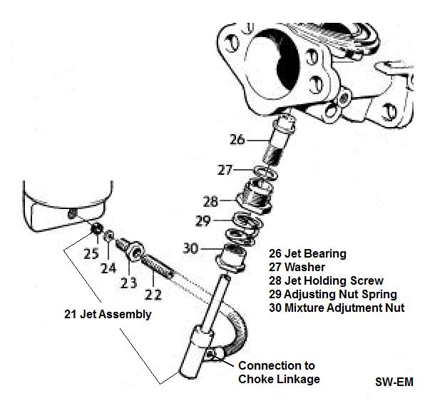
Exploded assembly diagram showing Jet and Jet Bearing Assembly installation into carb body. Jet
Holding Screw (also Jet Locking Nut)(28) secures Jet Bearing(26) into carb body (with lateral
clearance, allowing the ever-important
Jet Centering), and
Jet/Mixture Adjustment Nut(30) varies
the depth/height of Jet itself into the Bearing, allowing setting of initial
height and mixture, as well as subsequent fine adjustments. J/MAN
is secured from movement
during and after adjustments by preload from the Adjusting Nut Spring(29).
Initial Mixture Setting and Adjustment: When replacing a Jet with new, or just reassembling after a major service where the locations of these components may have been changed, initial set-up (for mixture) should start from: Jet flush with Jet Bearing surface, then lowered 2 full turns (or "12 flats" of the Jet/Mixture Adjustment Nut(30)). This will allow engine to start...then one can proceed with fine-tuning of the mixture. According to my careful calculations, the 12 flats of adjustment for (Threadpitch is 26) are 0.0769" down from flush...detailed also above under: Jet and Metering Needle Position Study, and also here: SU Jet Bearing and Supply Tube Notes
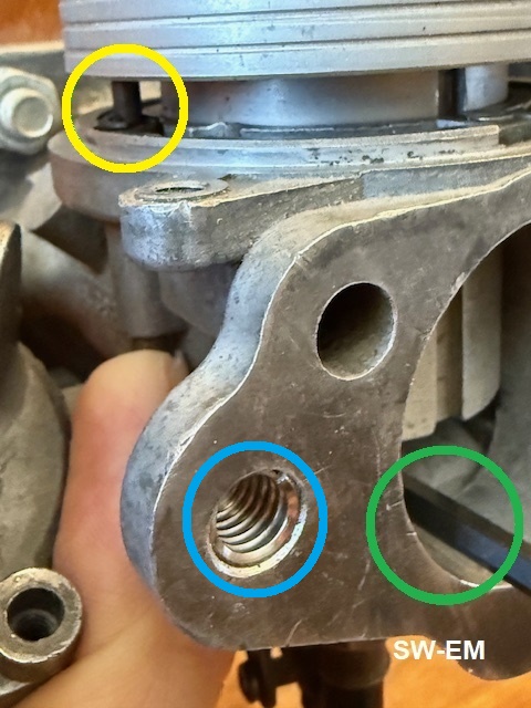
Here are pictures of a Jet Bearing removed from Carb Housing and by itself for clarity, with J/MAN(30) and Jet, but no Adjusting Nut Spring(29) or Jet Holding Screw(28) installed, to allow seeing the Jet Bearing threads.
 |
 |
| J/MAN is adjusted such that Jet is level/flush with Jet Bearing surface at Venturi (Yellow). Note number of Threads visible above JAN (Blue). | J/MAN is adjusted two turns (12 flats CCW) such that Jet is below Jet Bearing surface at Venturi (Green). Note number of Threads visible above MAN (Blue). This is 0.0769" down according to calculations. |
Properly installed Metering Needle. The MN shoulder is flush with Dashpot lower surface, as can be seen here, being checked with a straightedge.

Checking with a
straightedge, for a correctly installed Metering Needle, secured by a Setscrew.
SU KD and ZH Metering Needle Comparison:
I have highlighted OD at the Lifting Pin Mixture Test Point for the two typically fitted Metering Needles.
That "Variable-Venturi/Constant Velocity" thing!
Motorcycle carbs are often CV type, with the added detail that they combine the throttle and dashpot (and call it a slide!). I found this very good short explanation here: https://www.quora.com/How-does-a-constant-velocity-carburetor-work
-------------------------------
External material is attributed. This article is Copyright © 2026. Ronald Kwas. The terms Volvo, and names of other suppliers shown here are used for reference only. I have no affiliation with any of these companies other than to keep their products working for me, help other enthusiasts do the same, and also present my highly opinionated results of the use of their products here. The information presented comes from my own experience and carefully considered opinion (and fruitful little gray cells), and can be used (or not!), or ridiculed and laughed at, or worshipped, at the readers discretion. As with any recipe, your results may vary, and you are, and will always be, in charge of your own knuckles, and future!
You are welcome to use the information here in good health, and for your own non-commercial purposes, but if you reprint or otherwise republish this material, you must give credit to the author or link back to the SW-EM site as the source. If you don’t, you’re just a lazy, scum sucking plagiarist, and the Boston Globe or maybe Harvard wants you! As always, if you can supply corrections, or additional objective information or experience, I will always consider it, and consider working it into the next revision of this article...along with likely the unique metaphor and probably (likely) wise-a** comment, if I can possibly work it in!.