
The left backing light of an Amazon after '62.
Reverse Light Switches and Lighting Circuits
Dec2025, R. Kwas, [Comments Added!]
The left backing light of an Amazon after '62.
122 Wiring Diagram Excerpt
for Reverse Lighting
1800 Wiring Diagram Excerpt
for Reverse Lightong
1800E Wiring
Diagram Excerpt for Reverse Lighting
1800ES Wiring
Diagram Excerpt for Reverse Lighting
The 544 and 122 models up to approximately 1962, did not have factory Reversing Lighting as far as I'm aware. It had to be installed as an add-on, with a dashboard switch, putting it under manual driver control. After approximately 1962, the 122 model had a Reverse Gear Sensing Switch added at the Transmission, which made control of the Reversing lights automatic. When Reverse Gear was selected, Reversing Lighting would automatically come ON, by way of a Relay. The earlier Red over Red Taillight Lenses were replaced with Red over Clear, as seen above, or Amber, over Red, over Clear (as seen here: LINK), at that time.
1800s also had automatic control by way of switches at the transmission, but with variations in how the switches were implemented, and if Relays were installed. In early (carbureted) chassis, Reverse Lighting was powered directly, with no Relays installed, and in later (Injected E and ES chassis), both direct, and by way of a Relay has been observed.
I have collected switch variations associated circuits here, which one will encounter when troubleshooting non-functioning Rev Lights, or during restoration efforts.
As a general recommendation, if a Relay, with its inductive coil, is fitted to control the power to Reversing Lighting, the Switch which controls the Relay, will be subjected to a high turn-off voltage spike, which means its internal contact will have arcing and plasma, resulting in contact erosion. In later chassis fitted with the D-Jetronic Injection, such a turn-off spike has even been shown to be able to upset the injection system to the point of momentary drop-outs...how would you like to have your engine hick-up when you flash your Headlights or even just blow your Horn? This is not conjecture, but has happened! See: LINK
Therefore this statement: WITH FEW EXCEPTIONS, ALL RELAYS USED IN 12V AUTOMOTIVE CIRCUITS SHOULD BE RETROFITTED WITH SNUBBER DIODES AT THEIR COILS, TO MINIMIZE CONTACT EROSION AT THEIR CONTROLLING SWITCH (OR CONTACT), AND EXTEND THIS COMPONENT'S RELIABILITY AND SERVICE LIFE, OR, TO PREVENT MOMENTARY ENGINE DROP-OUTS IN FUEL INJECTED CARS! REFERENCE: LINK
For the completely different BW35 Automatic Gearbox, the Reverse Light Switch was implemented in combination with the Starter Enable Switch as discussed here: https://www.sw-em.com/Starter_Cutout_and_Reversing_Light_Contact_on_BW35.htm [Enable or Inhibit or "Lockout/Cutout"...it's all in the way you look at it!]
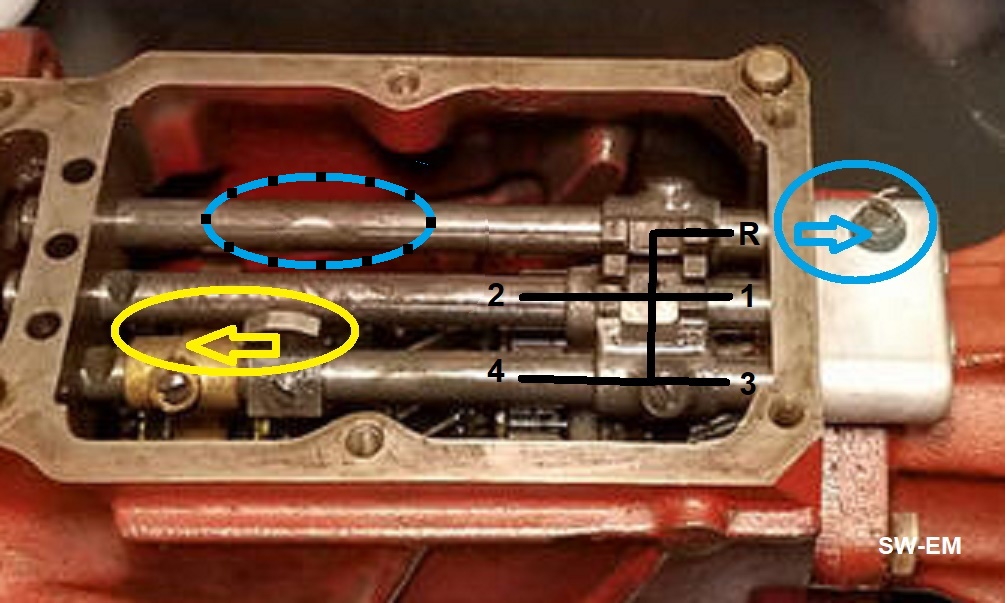
Topview of manual M40/41 Gearbox, cover removed, showing action of Gear
Selector Rods and Selector Pawl as the Shiftlever selects the various positions.

Reverse Light Control in a 122: Rear View of an M40, with early Reverse Light Switch fitted, as typically seen in 122s. The Rev Lt Sw connector is visible, at top of an Aluminum Switch Housing, located where it can sense the Reverse Gear Selector Rod protruding from the rear of Gearbox Case when Reverse Gear is selected, and complete a connection to chassis. This connection then completes the circuit for the Rev Lt Relay powering the Rev Lights. See Wiring Diagram Excerpt for 122 below.


Early style Reverse Gear Sensing Switch Housing, inside view, and in-place on
rear of Gearbox. There is not much happening inside there...but what's
happening is enough!
Reverse Light Switch Volvo PN 380360 consists of little more than a 1/4" terminal with a (conductive!) spring connected, molded into an insulated rubber holder, which is captured in the oval aluminum can secured to the Transmission Housing. As noted above, the electrical contact between the Reverse Gear Selector Rod and the Spring will benefit from a Snubbing Diode, which would minimize the arcing and resulting contact erosion.

As the Reverse Gear Selector Rod extends
from the Gearbox Case, from the Neutral
position, it contacts the spring of the Switch
and provides a chassis connection to the attached wire, completing the circuit
of the Reverse Light Relay. Simple and effective!
Early M40 Cover with no Switches fitted in Cover, but with brass plugs in their locations.


M41/OD combination from an early 1800. A Reverse Light control Switch
fitted to the Transmission top rear of Housing similar to those fitted to 122s
is evident, as is a 4th Gear OD Enable Switch on Transmission Cover with
rearward shifter assembly installed.
Early production 1800 Gearbox, cover removed, with Rev Lt and Pawl on the Selector Rod for 4th Gear Lockout/Enable* Switches. The alternate Rev Lt switch location, used in late production, employing a Selector Rail Pawl similar to the 4th gear Lockout Sw, is highlighted.
[*Lockout" or Enable...it's all in the way you look at it...!]

Gearbox Cover from a late production 1800, with both
Reverse Light Sw and
OD 4th Gear Enable Switches fitted.
Location of transmission activated switches (Reversing/"Backing" Light, OD 4th Gear Enable):

Sideview of Gearbox with OD, old style Reverse Light and 4th gear Enable OD control
switch fitted.
Late Production Gearbox Cover variation with Rearset Shifter and a switch sensing the Shifting Shaft.


Picture source: ...an Epay offering...gently used but sold "As-Is"...
Reference Information:
Reverse/Backing Light Control Wiring Diagrams:
Red is Battery power wiring.
Reference Info for Snubbing Diode added to Wiring Diagrams: LINK
122 Wiring Diagram Excerpt for Reverse Lights, showing Reverse Lighting control by way of a contact, which supplies a ground to the single wire connected to it, to energize and pick the Reverse Light Relay, which in-turn supplies fused power (Fuse2) to the two (15W) Rev Lights located in each Taillight Assembly (See also: https://www.sw-em.com/Amazon_Rear_Light_Fixture_Restoration.htm ). The single connection on switch is connected to chassis when Reverse Gear is selected, and activated directly by the Gearbox Selector Rail as shown above.

122 Wiring Diagram Excerpt for Reverse Lighting, Contact at Transmission
controls a Relay. The Switch contact will benefit from adding a
Snubber Diode! It can be
added externally at the Relay terminals. See:
LINK

1800s had a single Reversing Light incorporated into the Lisense Plate Lighting
Fixture.
1800 Wiring Diagram Excerpt for Reverse Lighting, showing Reverse Lighting control also by way of a (two-wire) switch located on Gearbox, which connects the power wire (Grn) to the (Grn/Brn), and thereby directly supplies power to the Revering Lights. The two wires and connections on switch are isolated from its own housing, but tied together when Reverse gear is selected, and these supply fused (Fuse2) power directly (no relay!) to a single (21W) Reversing Light in the central Lighting Fixture.
Beware! A second switch may be present on Gearbox cover! It is the 4th Gear Lockout/Enable Switch used for OD control, and covered elsewhere (See: LINK). Don't mix functions (or wiring!) of the two switches which may be present! Tip: Wire color codes are your friend!

1800S Wiring Diagram Excerpt for Reverse Lighting. No Relay means Switch
on Gearbox
has two connections, and does ALL the switching work!
1800E Wiring Diagram Excerpt for Reverse Lighting: Injected 1800s once again, were equipped with a Reversing Light Relay. located on the electrical panel in the engine compartment.

1800E Wiring Diagram Excerpt for Reverse Lighting. A Relay is
used, to control fused power (Fuse6) to the single central License Plate
Lighting and Reversing Light Fixture. The Reverse Lighting Switch contact
could also benefit from a Snubber Diode
added externally at the Relay terminals! See:
LINK
In the BW 35 configuration, the Reverse Switch is combined with Start Enable Switch, which controls the Start Enable Relay (Item 84).

The 1800ES had Reverse Lighting incorporated into the Right and Left
Tailighting Fixtures.
1800ES Wiring Diagram Excerpt for Reverse Lighting:

1800ES Wiring Diagram Excerpt for Reverse Lighting. Here, no Relay is
used, the Switch contact at the Gearbox switches fused Reverse Lighting power (Fuse6) to the
two Tail-light fixtures directly! As seen in the additional BW 35 configuration
in the Wiring Diagram, the Reverse
Switch is combined with Start Enable Switch, and also a switch in the Seatbelt Buzzer
circuit (Item 64).
-----------------------
External material sources are attributed. Otherwise, this article is Copyright © 2026. Ronald Kwas. The terms Volvo, and names of other suppliers shown here are used for reference only. I have no affiliation with any of these companies other than to keep their products working for me, help other enthusiasts do the same, and also present my highly opinionated results of the use of their products here. The information presented comes from my own experience and carefully considered opinion (and fruitful little gray cells), and can be used (or not!), or ridiculed and laughed at, or worshipped, at the readers discretion. As with any recipe, your results may vary, and you are, and will always be, in charge of your own knuckles, and future!
You are welcome to use the information here in good health, and for your own non-commercial purposes, but if you reprint or otherwise republish this material, you must give credit to the author or link back to the SW-EM site as the source. If you don’t, you’re just a lazy, scum sucking plagiarist, and the Boston Globe or maybe Harvard wants you! As always, if you can supply corrections, or additional objective information or experience, I will always consider it, and consider working it into the next revision of this article...along with likely the unique metaphor and probably (likely) wise-a** comment, if I can possibly work it in!.
