
Original source of this caricature: An old article I have yet to run across again...
Radio Notes
First published Dec 2017 R. Kwas
[Comments Added]
Original source of this caricature: An old article I have yet to run
across again...
Collection of information about Radios in a vintage Volvo.
------------------------------------
Radio Installations
Radio Interference
The 1800 Radio Wedge
Reference Information
Power line filters
-------------------------------------
PLACEHOLDER
With engine OFF, the DC Battery of a motor vehicle is a very good (dead quiet!) electrical environment...but when engine (both Ignition and Charging) Systems are running, that instantly turns into a pretty dirty environment! High frequency components from arcing brushes, Distributor Rotor and Charging Sys output current pulses (see Item 3 in particular!), need some quieting down, lest they get into our favorite music on the sound system. A Power Bus Noise Suppression is called for. See: Power line filters
-------------------------------------
Radio Interference and Minimizing it:
Interference is a general term for something other than the desired program material getting into a sound system, so it can be a result of many different types of issues. When addressing these issues, first source of interference must be determined and defined, as well as the path into the radio, because difference solutions must be used for the different kinds of interference and paths.
Conducted Charging System Whine is as the name implies, conducted through power line to radio...very different from, and not to be confused with Radiated Charging System or Ignition Whine picked up by the antenna...
Conducted Charging System Whine: Confirm by disconnecting Antenna (at the Radio). This removes that path into the radio. If engine speed related whine from charging system remains, the power bus of vehicle has this noise and it is coming into the radio and being amplified.
Conducted Charging System Noise Mitigation:
A
capacitor at D+ terminal of Generator (to filter the noise, with high frequency
components, coming from the arcing of the Brushes on the commutator), or BAT terminal of Alternator
to filter the current pulses of the rectified output phases.
Add in-line filter sized for the power current of the radio.
A (Filter) capacitor at the location where power is taken off and routed to radio.
-----------------
Radiated Charging System, or Ignition Whine: Charging System is less likely to radiate, but the fast rise-time of the Ignition Voltages also have high frequency components which reach into the Radio Frequency region and can get into a sound system by way of the antenna (and on AM more so than FM, because of AM's increased sensitivity and susceptibility to this type of Interference).
Received Charging System Noise Mitigation:
Install "Suppression Wires" (these are not of low resistance copper, but of
carbon impregnated fibers which put some resistance into the path, thereby
slowing down the Ign Spark voltages just enough to decrease/eliminate the RF
content. Another variation of this solution is as the factory installed...not
with the distributed Resistance of wires, but Resistor ends on the solid copper wires.
Resistor Spark Plug Connectors to suppress Ignition Noise: Bosch 1K Ohm Resistive Spark Plug Terminations, Spark Plug end.

Suppression end with 1KΩ internal resistance.
These have a threaded stud on the other end which screws into the conductor of
Ignition Wire.

Distributor Cap end of a Spark Plug Wire. Silicone insulation on a solid
copper conductor with the best terminations I have ever been able to find at a
"Speed Shop". Silicone wire is impervious to hydrocarbon attack (and
probably "Acts of God!"), so a rag and some carb cleaner cleans them up to look
like new! I have NEVER had one of these connections fail or replace one of
these wires! Yes, I said NEVER!

The conical end of the threaded insert locks the conductors of the Ignition Wire
into the seat of a metal insert molded into the plastic housing, so that when housing is pushed onto or
pulled off the Dist Cap, ALL of the forces are applied to the push-on connector
and NONE to the Wire/Connector connection...this is IDEAL! This is the absolute best
design I have found, because NO amount of manipulation or numbers of
removal/replacements of the connector will loosen, or stress or otherwise affect
the wire connection in the least! Unfortunately, I cannot find these
anymore, which doesn't do anyone else much good, but the reader should recognize the advantage of this design and look
for this type of design and implementation in any ignition wire terminations they are
considering...terminations which transfer or allow any forces to be transferred onto the wire are not long
for this world, and those who manufacture and sell these should be forced to
keep (and eat) them!

Complete Distributor with super groovy silicon insulation Ign Wires, complete with radio suppression terminations...ready for duty
in the Snow Weasel.
Ground the Vehicle Hood (additionally to the Hinges) by using a (low inductance) Braid to
Chassis. This helps to keep Ignition Noise (somewhat) confined to under the hood, and
away from the Antenna!
-------------------------------------
There is plenty of room behind the Dashboard of a 122 for a Radio, but when mounting the original equipment Radio in the stylish 1800, the room behind Dashboard is quite limited. OE radios were quite long behind the Dashboard and if mounted without any other consideration, would foul the Wiper Linkage, so installation into an 1800 requires a wedge to lower their rear-end and prevent this interference (it does also bring the Radio out from the Dashboard minimally).


The Radio Wedge.
-------------------------------------
Radio Delete Plate: This plate was installed at the factory to cover the (3) radio holes, and radio was typically installed by the dealer when order by the customer. The plate is held in place by two spring-clips inserted into the Radioshaft holes. Original examples are body colored, and with an embossed Volvo logo. These are somewhat rare, because the dealers probably disposed of many of them.


------------
Standard Dimensions for Vintage Volvo Radios:

Shaft to shaft centers is 5 3/8". Radio Dimensions are: W 7", H 2
1/2", D 5 3/4"

Bendix radio with Chrome escutcheon in place.

Chrome escutcheon alone on 1/4" graph paper. The center opening is 1 1/2"
X3 5/16",
and the center opening is biased off-center (down) by 3/32".
------------
Antenna: These were also installed by the dealer (per factory guidelines), when a Radio was ordered. If a Radio was fitted later or by someone other than the dealer, who likely was not following the guidelines, a high degree of variation in type and location occurs. If the reader can forward info on, or the location of one of these guidelines, please contact the author!
Link to VOC Forum Thread: Aerial Roof or Wing (American English: Fender): http://www.volvoforums.org.uk/showthread.php?t=263926
PLACEHOLDER FOR AFTERMARKET AMPLIFIED ANTENNA INFO.
Antenna wire is a special low loss coaxial cable consisting of an outer braid, and a miniscule (maybe 30ga.) inner conductor. That inner conductor is typically just flopping around loose inside a non-conductive tube and easily overlooked!
Below are pictured two standard antenna connectors...on the right one, the hollow inner conductor is clearly visible...that's where the inner conductor would be soldered.

Standard Automotive Antenna Connectors.
------------
Listening to ones own program material through the original equipment Radio.
The desire to fulfill this requirement has been addressed quite effectively and elegantly by guest contributor David Smith with an home-constructed MP3 player for AM radio. See Links below!
-------------------------------------
Additional Information:
Power line filters can consist of a simple bypass capacitor to chassis, a series inductor, or a combination of the two as shown here with pictures of samples.

Variation of Power Line Filters. When a chassis connection is required,
sometimes the metal case is the chassis connection point, sometimes a separate
wire comes out of the insulated housing... Note also that the simplest
capacitor to chassis looks suspiciously like a "Condenser" one sees at a
Distributor with "Points"...that's because they are very similar, and have
a similar function, however must be rated somewhat differently (Ign capacitors
are high Voltage >600V), Low Capacitance (.22uF) types, while Radio suppression
are hi capacitance (2.2uF), "low" (100V) Voltage types...a tenfold difference.
Additional notes [and stupid, but
true(!) comments] on the filtering components pictured above, which the sharp observer may
notice:
1. This might be a coil or a capacitor (a check with a DVM would clear
that up quickly).
2. Since only one capacitor is evident, it is an RC filter, not a PI
configuration.
[3. I thought the point was to
suppress engine noise, not the engine itself! ...and...if you have to label your
own product "High Quality...", it probably isn't, but rather a
just-barely-good-enough, and
as-cheap-as-we-could-possibly-make-it-piece-of-china-s**t! (Sorry!)]
--------------------------------------
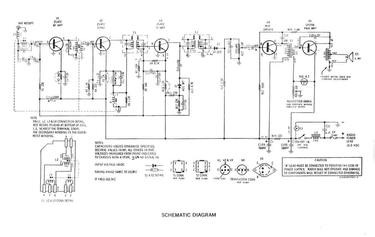
Link to Bendix Radio Circuit Diagram: AM Radio (Bendix?) (These radios could pick up Finland at night!)
Link to Motorola Radio Circuit Diagram: AM Radio (Motorola?)
Link to Radio related accessories info from 1973: http://volvo1800pictures.com/document/assessories_73/accessories_1973_group_50.pdf
Sub-page: MP3 Player for Volvo AM Radio by SW-EM Guest Contributor David Smith (A neat project for the hands-on electronics individuals, which ties modern sound storage and players to the AM radio in a vintage car.)
Sub-page (kindly supplied by Graham C.): 1968 Volvo FM-AM Radio Owner's Manual and Installation Instructions.pdf
-------------------------------------
KA1-RBP Mobile Station:
PLACEHOLDER FOR AMATEUR RADIO INSTALLATION AND OPERATION IN THE SNOW WEASEL:

A tunable LC filter for difficult noise cases...installed from Gen/Alt
output, to chassis, it shunts frequency range it is tuned to,
to chassis,
to keep those frequency components from getting out, possibly radiating (or
conducting) along
wiring, into Comm equipment.
-------------------------------------
External material attributed. This information is Copyright © 2024. Ronald Kwas. The terms Volvo, Bendix, Motorola are used for reference only. I have no affiliation with any of these companies, other than to try to keep their products working for me, help other enthusiasts do the same, and also present my highly opinionated results of the use of their products here. The information presented comes from my own experience and carefully considered opinion, and can be used (or not!), or ridiculed and laughed at around the water-cooler, or worshipped, at the readers discretion. As with any recipe, your results may vary, and you are, and will always be, in charge of your own knuckles, and future!
You are welcome to use the information here in good health, and for your own non-commercial purposes, but if you reprint or otherwise republish this article, you must give credit to the author or link back to the SwEm site as the source. If you don’t, you’re just a lazy, scum sucking plagiarist, and the Boston Globe wants you! As always, if you can supply corrections, or additional objective information or experience, I will always consider it, and consider working it into the next revision of this article...along with likely the odd metaphor and probably wise-a** comment.
