Fuel Tank Notes
2021-2023 R. Kwas [Comments
Added]
Fuel Tank Configurations
122 Sedan Tank
122 Station Wagon
Tank
122 Wagon Fuel
Cap is non-vented
1800 Tank
1800E Tank
Pick-up Tube and Anti-Slosh
Compartment
1800ES Tank
china gets it
wrong...again!
Various Tank
internal plumbing Configurations
Injected Fuel Tank
Plumbing
Versions
of Tanks for Injected Models
Replacement Sump-plug
Common Fuel Tank Issues
Tank Venting
Correct
1800 Tankseal Installation allows Atmospheric Venting
Solder
Joint failures on 122 Sedan Tank
Gas Caps
Derusting Tank
Reference Information
Links
Mr. Goodenoughwrench
-------------------------------
Fuel Tank Configurations:
122 Sedan Tank:

The Volvo Fuel Tank configured for use in an Amazon. Notice the arch
clearance on left...this is a strong suggestion that the same tank pressings were also
used for the 1800, where the vent fitting visible in the 1800 Tank picture, is located there (filler pipe enters Tank
below seam).
-------------------------------
122 Station Wagon Tank is
somewhat unique, and shallow, and it looks like the
(side) filler pipe is shorter than on the sedan...this could be the explanation why
there is typically a fuel stain under the Fuel Filler of Kombis (and it is
important to assure the Fuel Cap has a good seal to prevent this leakage and
resulting staining).
The important difference to note in Sedans vs. Kombis: Fuel Cap on the Kombis are unvented to prevent spillage
(there is a vent in the filler tube!), unlike the vented Fuel Cap of
Sedans.

Picture Source:
https://vp-autoparts.se/sv/artiklar/bensintank-amazon-220-kombi.html
122 Wagon Fuel Cap is
non-vented!
My posting to thread: Rebuild Gas Cap
https://www.swedespeed.com/threads/rebuild-gas-cap.640073/#post-7772390
"Wagons never had locking caps, so I deduce this is an aftermarket one which
a PO or you have installed...and knowing it's an aftermarket one, I also deduce
that it is vented, which they typically are...and herein lies the rub, this does
not play well with the relatively flat Tank and Filler, and is likely cause of
your leakage! Factory wagon Fuel Caps were not vented...that is not to
say Kombi Tanks were not vented...they were!...but in the filler neck and
occurring behind the Cap (which must do its intended function without making a
mess). I suggest your leakage is from the vented Cap which you could address. I
would suggest rebuilding it, and while you have it apart, you will undoubtedly
see the venting provision, which you should defeat before reassembly. Please
take and post pix of Cap rebuilding!
Naturally, the sealing of the rubber gasket between Cap and Filler is important
and must function well. You may need to adjust or replace with thicker to assure
sufficient preload.
From the Exploded Assembly Diagrams at GCP.se site:

Tank venting is routed from Fuel Filler, behind interior panel, not by way of a
vented Fuel Cap!

...not an unusual Amazon Kombi look...
Link to Swedespeed Forum thread Wagon leaking fuel cap fixed: https://www.swedespeed.com/threads/wagon-leaking-fuel-cap-fixed.652798/
When an OE Filler Cap is not available..."Rustinmotion" pic permission
requested.

-------------------------------
1800 Tank:

1800S Tank, with Filler entering the Tank below seam and just above it
the Vent connection. Note area for 122 Filler location.
See also:
1800 Tankseal
Installation allows Atmospheric Venting
Picture of inside of tank by BF Candela, permission requested.
Inside of an 1800 Fuel Tank showing the pick-up tube entering at the front,
curving down to the bottom, and two anti-slosh baffles.
It looks like the Pick-up Tube may have been replaced.
Good Thread on Swedespeed:
https://www.swedespeed.com/threads/fuel-tank-fitting-removal.601471/
-------------------------------
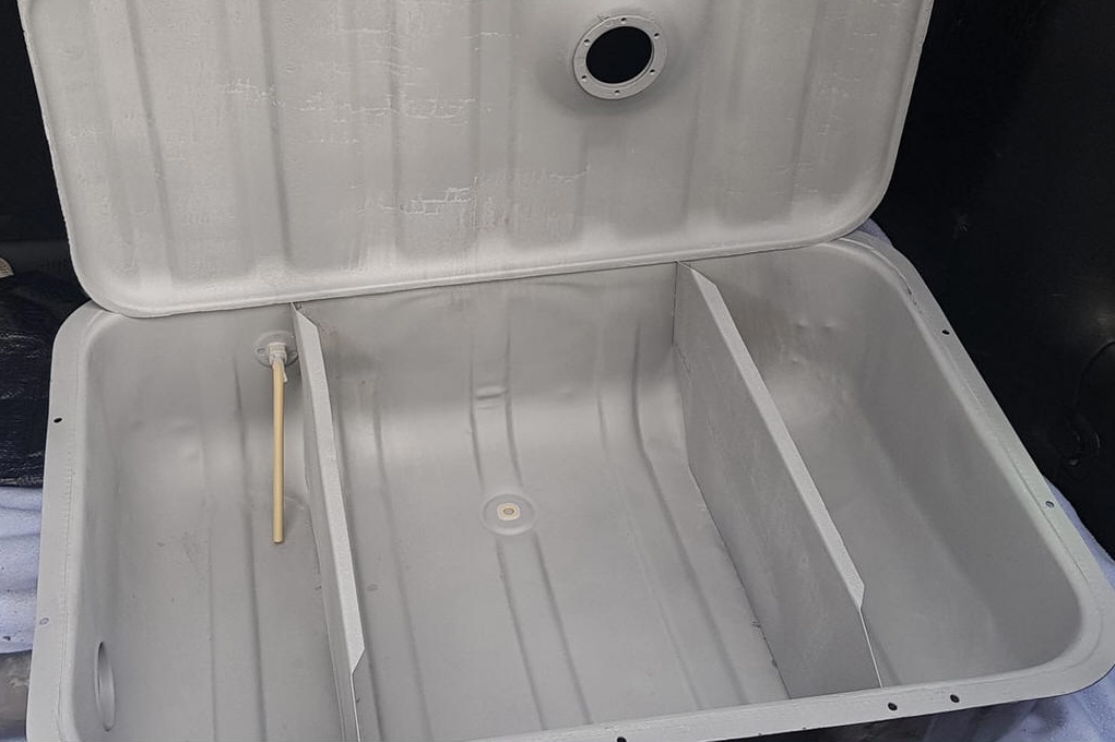
1800E Tank:
Pick-up Tube and Anti-Slosh Compartment
Picture of the inside of a tank from an injected 1800, showing Anti-Slosh
Compartment with
Fuel Pickup. Second picture shows
Fuel Return from Fuel Pressure Regulator
of the
Bosch
D-Jetronic Injection System.
One of two big general tank baffles is visible.

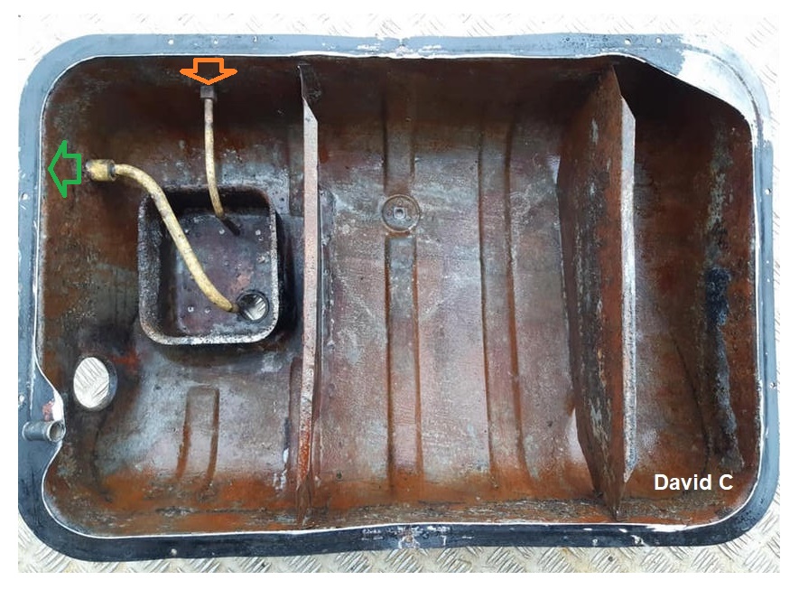
Internal Anti-Slosh Compartment is clearly apparent. Fuel return
is at front-facing side of Tank, and it
feeds into bottom of ASC (Orn),
as well as replenishment ASC from main Tank volume. At
Green, the Fuel Pickup tube also
feeds from the very bottom of ASC, and no prefilter is present (as with the
later ES and replacement Tanks). Source of picture:
http://www.gas-tank.com/Links2009/Volvo.htm
-------------------------------
1800ES Tank with in-tank Prefilter (Version
3, 1973 only!)
The following four pictures and info for 1800ES tank were kindly supplied by Jim Perry:

'73 ES Tank topview, visible is the Senderhole.

Same Tank bottom view, showing both the central Drain, and the Sump with
Prefilter location, and also a good dent which one can suspect as part of the reason Jim
replaced the Tank!

Prefilter can be simply pulled from Feedtube, after removal of Sumpplug (Bruce K
noted that a 3/8" ratchet extension did not fit the Sumpplug...a
sacrificial one had to be ground slightly to make this possible, so it is likely
a metric nominally sized Plug...and 3/8" is a bit bigger than 11mm!). Any particles of contamination which have been sucked onto Prefilter fall into
the sump when suction from the pump is no longer present, so will be inspectable
after removal of Sumpplug. See an inside view of this style Tank below!
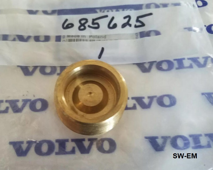
china gets it wrong...again!

Note the difference both in the threading and tool necessary for
installation/removal in the OE brass Sump-plug, and those of replacement Tanks
[china's finest work strikes again!].
Beware: You can use a 3/8" square socket drive to remove
the original Sump-plug, but if you use it alone it will fit
too loosely, and with the torque necessary to break loose a Plug which
has been in place for a loooong time, will just strip out of the square
drive hole and deform it. This
can be seen in the picture
above! The Plug of soft brass, and that
square drive hole is actually 7/16" or 11mm, so to assure a more
correct fit of the 3/8" drive, and prevent damage to the plug when wrenching
on it, I suggest to use that 3/8 socket drive PLUS a thickness of
strategically cut sheet metal (like a Coke or Coors can*), held in
place on the flats of the drive with tape), to make up the difference!
Simple!
* ...but it should be from a product with a name starting with "C"!
----------------------------
Various Tank
internal plumbing Configurations:
For carbureted models, the configurations are fairly simple, with a Pick-up Tube
coming in the Tank front side, and making a turn down towards to feed fuel from the Tank bottom.
I have tried to collect some internal Tank pictures here, and where I have yet
to get a picture, I have included a graphic representation as near to the actual
as I could deduce (any individuals who cut open a Tank not shown here, are
invited to contribute some pix, thanks!):

Part of a nicely cleaned carbureted Tank, with what looks like a replaced
Pick-up Tube.
Injected Fuel Tank Plumbing, 3
Port Fuel Pump (with Prefilter in replacement Tank):

Dan G provided this nice clean picture of his '71 1800E with a replacement
Tank*, showing the feed (Green)
to the (3 Port) FuPu from the side, FuPu outfllow
(Blue) to FuFi and beyond, and
the bypass outflow from Pump into "T" fitting
(Orn) , joining the Fuel Press
Reg Return from engine compartment (which is obscured).
* Notice that this arrangement is with a replacement Tank. These Tanks
are all configured with an internal Prefilter, so the external FuFi is plumbed
post-pump...since there is no Prefilter in the original E Tank, the FuFi
would need to be located before Pump.
Versions of Tanks for
Injected Models, internal Tank configurations got more complicated, with the
addition of the Fuel Return Line
from the Fuel Pressure Regulator, an Anti-Slosh Compartment
and on the last models a Prefilter
with Sump. Versions 1-3
known to the author are shown here (if the reader can help with internal
pictures of various configurations of OE Tanks, please e-mail!):

Three Versions of Tanks.
Version 3. Pic of a cleaned the '73 ES (Version 3) Sump with Plug removed, so that
angle-cut Pickup Tube with shoulder-stop for the Prefilter and soldered-in brass Sump
fitting are all nicely discernable. Picture by Bruce K. and reposted with
his kind permission.

Pic Source:
https://www.swedespeed.com/threads/fuel-tank-fitting-removal.601471/
David Critchley picture of what he stated to be a Tank from his '71 E
(which should be a Version 1 style), used with his kind
permission...but this looks to the author like a late ES Tank with the Pick-up Tube,
Pre-filter and Sump arrangement...now I'm confused!
[Could it be that the
tank had previously been replaced with a later (Version 3) one...?...this could
not be confirmed by David.]
Replacement Sump-plug on Version 3 Tank:
Visible is the raised center area which holds the plastic Pre-filter in place on
the pick-up, and the lowered sump which collects any debris that drops from the
Pre-filter when FuPu is depowered and suctions stops.
Friendly Tip: When replacing the Sump-plug, double-check compatibility of
threads! See above!
Link to:
D-Jet Comparing Early vs
Late Fuel Delivery...it can get complicated!
Replacement Tank
Installation Notes:
Fuel Tank replacement plumbing by Mr. Goodenoughwrench:
A replacement Tank (which apparently all have the side-located feed, plus
front-located return necessary for FI) has the feed plugged, and some custom
plumbing feeding from the return (which apparently also works), supported by a
less than impressive wire, which looks like it came off a bundle of asparagus
from the grocery store...hmmm! David Smith picture used with his kind
permission.

PO (aka Mr. Goodenoughwrench) strikes again! I spy late Trailing arms with
Poly bushings, and a 3/4" IPD rear anti-sway bar!
----------------------------
Common Fuel Tank Issues:
Tank Venting:
Fuel Tanks for non fuel-injected vintage Volvo cars are, and must be(!), vented to
atmosphere. Failure to have this condition, by for instance, replacement
of an incorrect Fuel Filler Cap can/will cause problems...
Correct 1800 Tankseal Installation allows Atmospheric Venting:
Here, an example of the important requirement for an atmospherically vented Fuel Tank
for a carbureted 1800:
Mike Haag pix, reposted here with his kind permission.

Replacement Rubber Seal installed as one might reasonably believe it should
be...but this is wrong...read on!
My response to a question of
 about "loud woosh sound" when opening 1800
Fuel Filler Door:
about "loud woosh sound" when opening 1800
Fuel Filler Door:
"These cars had no evap recovery/control systems, and the 1800 Fueltank (just
as the 122) should be vented to atmosphere...wooshing sound is escaping of
pressure due to temp rise and resulting evaporation...and the ENTIRE fuel sys
before FuPu
is subjected to that pressure!
(Edit: CORRECTION: ...entire fuel Sys...not only
before FuPu, but also
downstream since both Checkvalves
in Fuel Pump would allow flow in that direction), so you might experience some
(undesirable) leakage in the plumbing or engine compartment!
Conversely, when
driving, you might experience fuel starvation issues when a vacuum is created in
Tank because it can't draw make-up air through that Cap and Seal...so I'm with Mike...I'd simply enlarge that central securing hole (or add some
slits) so it doesn't seal quite as good. "
This was not the remedy for this
issue...read on!
[The above info is all correct, and
this issue was caused by owner reasonably following Volvo's Exploded
Assembly Diagram...but the solution was even simpler: What is shown in the
Exploded Assembly Diagram is slightly deceiving, and maybe of an earlier design
(or just plain wrong).
Part 27 is the metal cup behind/above the Rubber Seal (35 [plain] OR 35A
[cupped, which may have been a later design improvement]).
I have amended Volvo's Exploded
Assembly Diagram below, and added the cupped
Rubber Seal(35A)
as it should be located and be installed...by
gluing
it, cup down,
onto the flat area of the Metal Cup(27)! The Metal Cup is assembled, cup
up FIRST, with Washer(29) and Cotter Pin(30) holding it in place on the Pin
which extends down from the hinged Fuel Compartment Door [Cap(26)], THEN, the
Rubber Seal is glued in place.
The reader will notice that when
correctly assembled in this manner, the Tank is indeed vented to atmosphere, and
NO wooshing (in either direction!) should ever occur!

Excerpt of Volvo's exploded assembly diagram, amended for clarity by the author,
showing the Cupped Rubber Seal(35A).
Although one might mistake Item 27 for the Rubber Seal,
[IT IS NOT!] ...it is the metal cup
which supports the Seal (Item 35), and unfortunately, the way Item 35 is
originally shown in the diagram,
it looks like only a flat circular gasket and not with a cup-form (pointing down!) as
seen in the Correct Assembly shown below. I have added what I believe to
be a better representation of the Seal in the highlighted area at
35A.
With the Rubber Seal (35) installed as shown below, the central hole is
unblocked which allows breathing of the Tank and no pressure or vacuum build-up
or wooshing effect.
Correct Assembly: The Washer (29) and Split Pin (30) are to
secured the Cap, lower (27), with cup up, and the Gasket (35, Cupped
Rubber Seal) must be glued to Cap with cup down. Of course, since the central hole is not used to
retain Seal when mounted like this...it is free to allow venting to take place through the
hole and past the Pin to Cup mount, and pressure/vacuum in the Tank is
prevented!

Correctly installed Rubber Tank seal (35). Glued in place with convex (and
venting hole) down.
----------------------
Solder Joint failures on 122 Sedan Tank:
Screenshot from
Pieter Beeckx
video used with his kind permission :

Common weakness of the 122 sedan Fuel Tank. Soldered joint at Filler Neck
to Tank. The solder fractures due to weight of the fuel filler pistol
being hung onto the filler.
This is less of an issue in other models, where the filler is better supported
in the body. A leak-test with water verifies the fractured solder joint at Filler Neck root.
My comments to a Faceplant
post.

" Leakage as shown in
Pieter's video is absolutely typical...and due to cumulative fatigue of
years flexing the joint from hanging the
fuel-filling pistol onto the fuel filler...that is only a solder joint,
and it gets stressed and shows once again, that solder just isn't mechanically
strong and up to the task long-term... My Tank had a cracked solder joint there also (although
I was not particularly rough with hanging the fuel filler on there!)...I resoldered it,
but noting the long-term weakness, added strengthening gussets (see below) to significantly improve the mechanical support of the
filler-neck.
If you cannot solder
(for which tank must be COMPLETELY empty and vented, or baked in the sun until no more
strong fuel smell
confirms non-flammability!), OR you don't want to remove Tank, you can
temporarily seal fuel leaks with fuel compatible (silicon) RTV (like
Dow-Corning 730 Fluorosilicon formulation, NOT 732 general purpose
[which is not hydrocarbon
compatible!]) ...until it can be repaired right...but
again, I highly recommend installing strengthening gussets to support
filler neck or this condition can easily return! There's not a lot
of room, but enough...see below for a sketch of what I installed last
time my Tank was out. "

Rick Watson Picture used with his kind permission.
-------------------------------
Answer to Faceplant
request for
details on gussets I mentioned.
"Sorry no pix, I did this long ago, but I remember the design well...2
gussets had to be fairly small to clear the bulkhead Fuel Filler passes
through, plus the trunk [floor] rises back up, so it must clear that also...here is
a conceptual sketch which captures it well...I used ~20ga sheetmetal and
soldered it into place [2 are added!]. Cheers
Edit: It was tight getting the tank with gussets back in place, so I suggest
you make some trial gussets of cardboard, tape them onto Filler and trial
fit Tank back into place to assure they don't foul on the bulkhead during
installation...there's not a lot of room!...only when you're happy with
installation clearance, you can make it of metal and more permanent...other
option of course is to cut clearance into the bulkhead, but I didn't feel it
was necessary..."


Gussets support Filler Neck to seam, here. The fuel filler protrudes
through inner bulkhead, then outer body. No supporting rubber surround is
present yet in this excerpt of the R. Watson photo.
------------------------
Gas Caps:
From Thread:
http://www.networksvolvoniacs.org/index.php/Spezial:AWCforum/st/id6591/Vacuum_im_Tank.html

Locking Cap partially disassembled, showing what certainly looks like a possible vent.
Picture credit: Rainer of the Volvoniacs Forum.
---------------------
Derusting Tank in preparation for
internal sealing
If you are going to DIY...
Internal Tank cleaning of rust...strapping the tank to a cement mixer, with a
few of handfuls of course stones for abrasive.
When using tank sealers, like POR15 subsequently, its critical to follow the
sealer manufacturer's instructions to the letter...take no short-cuts,
make no "judgment calls"!
Peter Bellinck photo...used with his kind permission!

Maybe unique, "rustic", and noisy, so should definitely be done "behind the
barn", but a very effective way of prepping the Tank interior for sealing.
----------
Great comments to the Tank sealing process by "142guy" here:
https://www.swedespeed.com/threads/fuel-tank-fitting-removal.601471/ see
Posting #20!
-------------------------------
Reference Information:
Update: Notes on a
conversation with Joseph Moyer, long-time owner/operator of Moyer Fuel Tank Renu
(http://www.gas-tank.com ). They
bake out each Tank and prep by blasting, to give their baked-on internal plastic
coating the best adhesion possible, and their work is guaranteed for life.
They are located near Pittsburgh PA. Mr. Moyer tells me that the Fuel
Filler behind the license plate of seventies GMs was similarly susceptible to
fractures on the soldered-on filler pipe (soldering is apparently the typical
manner in which fittings and pipes were connected to steel fuel tanks in the
past. He has also reinforced such weaknesses with gussets
[I guess great minds do think
alike!...just saying!]
Knowing the internal condition of my 1800ES Tank, I intend to use their
service when the ES gets next recommissioned...instead of changing to a new, but
chinashit replacement Tank, guaranteed to last from 11 'til noon!...and he tells
me the mounting holes of chinashit tanks often don't line up!...more of
china's finest work! Watch this
space for results of the experience!
-------------------------------
From a conversation with Don Thibault (www.p1800.com
) :
He stocks OE Tanks and just replaces them now..."they're all going on 50
years old now..." ...he's got a valid point there,
but not if the chinese, in their neverending quest to cheapen things up, get it
wrong...like here:
china gets it wrong...again!
-------------------------------
Links:
Fuel Gauge Information and Notes
-------------------------------
Mr. Goodenoughwrench
SW-EM...(occasionally) also the home of:
: 
----------------------------------------------------
External material
sources are attributed. Thanks again to all contributors of pictures and
information! Otherwise, this article is Copyright © 2020-2026. Ronald
Kwas. The terms Volvo, and name of any other companies or
individuals included here are used for reference only. I have no affiliation with any of
these companies other than to try to keep their products working for me, help
other enthusiasts do the same, and also present my highly opinionated results of
the use of their products here [like the
fact that china got it wrong again!]. The information presented comes from my own
experience and carefully considered opinion, and can be used (or not!), or
ridiculed and laughed at, or worshipped, at the readers discretion. As with any recipe, your
results may vary, and you are, and will always be, in charge of your own
knuckles and future!
You are
welcome to use the information here in good health, and for your own
non-commercial purposes, but if you reprint or otherwise republish this article,
you must give credit to the author or link back to the SwEm site as the source.
If you don’t, you’re just a lazy, scum sucking plagiarist, and the Boston Globe
wants you! As always, if you can supply corrections, or additional objective
information or experience, I will always consider it, and consider working it
into the next revision of this article...along with likely the odd metaphor and
probably wise-a** comment.
