
Source: 1966 122S owners manual
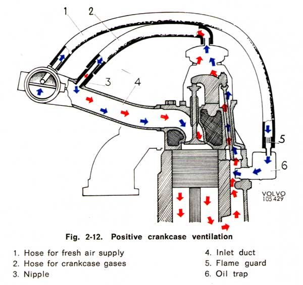
Positive Crankcase Ventilation (PCV)
Diagrams and Notes
First published 2015 R. Kwas updates
on-going [Comments Added]
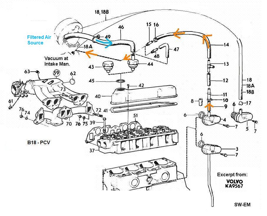
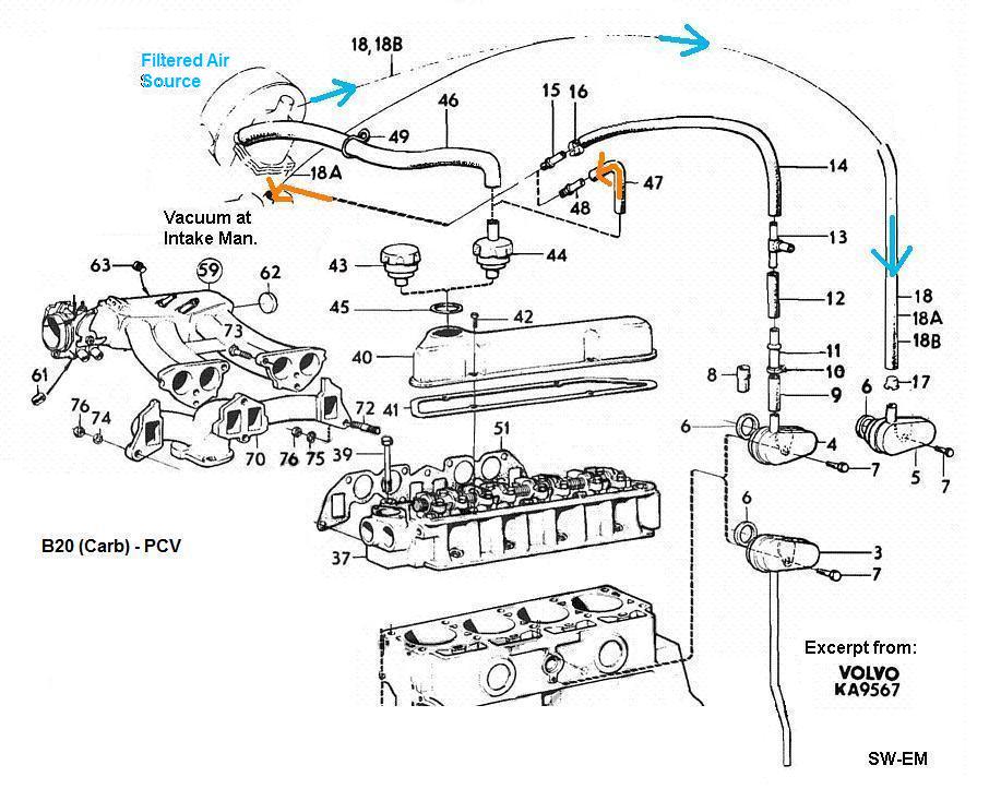
The PCV system is occasionally the source of
some confusion because you will notice that between the B18 and B20 diagrams
below, the direction
of flow (of gasses) at oil filler cap changes (and the PCV Valve is eliminated on the B20). The direction is not critical, in
either case, the important thing/principle for a properly working PCV system is
a filtered
fresh air source to mix with crankcase gases, and a (flow-limited) path to the intake manifold
to extract the mixed gases for burning.
Note that plumbing of PCV Sys is often combined with that of a Brake Booster, which also needs Intake Manifold Vacuum to operate...there is nothing wrong with this as long as direction of flow, flow limitation, and safe conditions if a backfire were to occur in the Intake Manifold are observed and satisfied (this means a check-valve must be present, which only allows vacuum, and never pressure from such a backfire, to be applied to the Brake Booster).
Problems occur typically when the extraction path is blocked (fouled PCV valve [No.4 on B18] or flame guard or nipple [B20]), this leads to crankcase pressurization and oil leakage around Oil-Filler Cap or other points of easy exit.
Note: Before there was Positive Crankcase Ventilation (PCV), there was Open Crankase Ventilation (OCV).
B18 PCV
Configuration
B20 (Carbureted) PCV Configuration
B20 (Fuel Injected) PCV
Configuration
Links
PCV Rattle Trap
Additional Information
Open Crankcase Ventilation (OCV)
Oil Filler Caps
Non-Standard Crankcase
Ventilation
Example of Creative (but wrong!) PCV
Plumbing
Reference Information
Oil Trap
Pipe Dimensions
Clogged Flame Trap
Crankcase Pressurization
PCV Options [These are excerpts from factory
drawing showing variations of PCV,
including B20A, which were not imported into the USA.]
--------------------------------------------------
Key:
1. Flow limiting orifice.
2. Metal mesh filled Oil-Filler Cap
3. Oil Trap to Intake Manifold connection
4. PCV (one-way) valve (see also:
PCV Rattle Trap)
5. Flame guard
6. Oil Trap
Source: 1966 122S owners manual
--------------------------------------------------
B20 (Carbureted) PCV Configuration:

Source: 120 Series Intereurope workshop manual
162
--------------------------------------------------
B20 (Fuel Injected) PCV Configuration:
Source: 1971 1800E Service Manual
See also PCV Options below.
--------------------------------------------------
Good info copied from an excellent site on the D-Jetronic Injection: http://members.rennlist.com/pbanders/PCV.htm
PCV Valve Operation Modes
This mode corresponds to the idle condition. The pressure differential presses the disk against the intake manifold side seat, where the metering slots permit a regulated flow of gasses into the intake manifold.
This mode corresponds to over-run (coasting in gear with the throttle closed). In over-run, manifold vacuum can exceed 20 in. Hg. The pressure differential presses the disk against the intake manifold side seat, where the metering slots permit a regulated flow of gasses into the intake manifold. Blow-by is minimal as combustion is at a low level.
This mode corresponds to part-load conditions. The pressure differential presses the disk against the intake manifold side seat, where the metering slots permit a regulated flow of gasses into the intake manifold.
This mode corresponds to heavy load to full-load conditions. Here, most of the pressure differential that opens the PCV valve comes from crankcase pressure. The pressure differential presses the disk against the intake manifold side seat, where the metering slots permit a regulated flow of gasses into the intake manifold. If the blow-by volume exceeds the ability of the PCV valve to draw in the vapors, the excess blow-by flows back through the crankcase fresh air intake system to the air cleaner box, where it is pulled through the throttle body and into the cylinders.
This mode corresponds to an intake backfire condition. Here, the high positive pressure in the manifold presses the disk tightly against the crankcase side seat, sealing the PCV valve and preventing flame propagation into the crankcase to prevent an explosion.
--------------------------------------------------
Link to interesting Brickboard thread: http://www.brickboard.com/RWD/index.htm?id=920391
Link to related thread for replacing the fresh air hook-up from front filter with a mini fresh air filter mounted on the oil filler cap : http://www.brickboard.com/RWD/index.htm?id=1184285 ..this prevents condensate and/or oil in the front filter!
Not an uncommon posting, showing what happens when PCV is clogged, resulting in crankcase pressurization and oil leakage: http://www.brickboard.com/RWD/volvo/1439938/140-160/oil_leaking_like_crazy_front_timing_cover_felt_seal.html
--------------------------------------------------
PCV Rattle Trap: https://forums.swedespeed.com/showthread.php?593015-PCV-rattle-trap
My response: "PVC Valve rattle is a condition (annoying,
but otherwise not really harmful) which occurs when the frequency of pulses of
vacuum at idle is equal to the resonant frequency of the return Spring and Mass
of shuttle/ball in the Valve, in combination with the volume inside the PVC
plumbing...its a pretty specific confluence of conditions (like hitting the
mechanical lottery!) that happens occasionally (but only at idle, where
frequency of the individual pulses are slow enough, and don't yet combine into a
steady vacuum)...change any one of the critical parameters, and it will
stop...so much for the theory (my good friend was a physics teacher, so I had to
get this right or I would never live it down!)...
in practice, the simplest solution to prevent resonance, is to just change the
exciting frequency a bit, by just changing the idle RPMs a little (that's what
did it on my 122/B18)...if that winds up being too high or too low to be an
acceptable solution, another possible preventative is limiting the excitation
pulses the valve is seeing, can do it too (by adding a partial flow blockage
[washer] with a hole in-line into the PVC plumbing to partially orifice block
it...to see if this might help, simply squeeze the line partially shut to try
it)...or creating a little buffering volume in the PVC plumbing by installing
two flow limiting orifices, one at the manifold, one at the Valve, or plumbing
in another length of (dead-ended) tubing with a "T" (kinda like the expansion
tank on a furnace), finally, just replace the PVC Valve...what are the chances
that replacement Valve will be resonant also...but where's the fun in that?
Edit: I guess you already tried replacing it, and it still rattles...try
replacing with a different style/manufacturer Valve, or I guess it would be time
to try one of the other suggested solutions...
"
--------------------------------------------------
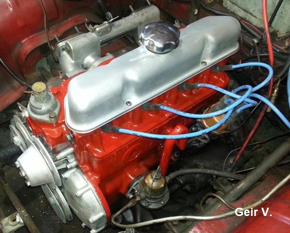
Open Crankcase Ventilation (OCV):
Before approximately 1964 (market dependent), the crankcase was vented to atmosphere by way of a tube, with no oil trap, but with tube shaped with an uphill section to prevent oil from simply running away to be lost, followed by a downhill section, which finally opened to atmosphere next to the oil-pan. This tube was paired with the plain, vented Oil Filler Cap. Both are visible in this picture by Geir V.
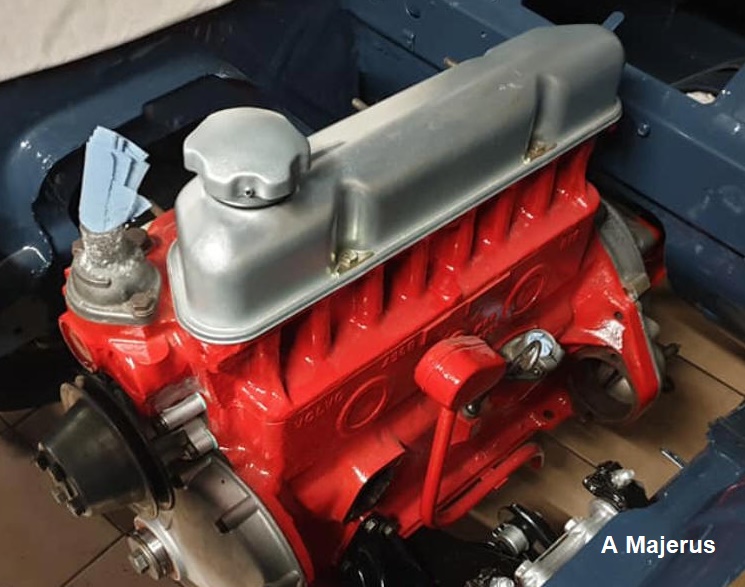
Another variation of OCV, this time again with an open down-tube, but with an Oil-Trap at the crankcase. This would have also been combined with a plain, vented Oil-Filler Cap, as shown. Picture credit: A. Majerus.
Oil Filler Caps were part of the Crankcase Ventilation System (Open or Positive).
Two types of Oil Filler Caps were fitted. The earlier plain top one, shown on the left, filled with a filtering metal mesh, and which allowed flow in both directions by way of under the flutes, and the later, also filled with mesh, which had a fitting for the PCV plumbing. Direction of flow in the later Cap was determined by the configuration of the rest of PCV system, as shown above.

Oil Filler Caps. Picture credit: Derek
Modifications:
Shown here is an Oil Filler Cap with a separate filter installed. This is a favorite solution for allowing the crankcase to breathe fresh, filtered air, without allowing oil to get on induction Air Filters (which can happen during High Crankcase Pressures - see above, or high blow-by), or when a fresh air fitting is not available, such as on non-original equipment induction Air Filters.

Oil Filler Cap with mini fresh-air filter. Picture credit: Derek
----------------------
Non-Standard Crankcase Ventilation: (Sometimes they get it right, sometimes not!)
Creative and Acceptable PCV Plumbing:
A nicely racing-prepared '69 Amazon, driven in the Norwegian historic racing series. The car was shown at the annual Oslo Motorshow. We can see a custom vented alu PCV catch container in the normal Battery location. Note also the Dual Weber side-draught carbs with velocity stacks, necessitating a custom inner fender clearance pocket. Cable activated Clutch and dual Brake Master with a tandem Booster are also in evidence.
Erik Skifjeld Endre picture used with his kind permission.

Custom PCV System for vintage competition.
Creative (but wrong!) Crankcase Venting Plumbing, can cause symptoms affecting idle, to oily gunk in carbs or Air Filters, to oil leaking from Dipstick, to name just a few! Here are some examples of "owner engineered versions" of NSCV (Non-Standard Crankcase Ventilation).
On the non-standard arrangement shown below, upper (at Oil Filler Cap), and lower (at Oil Trap) are tied together. Without further modifications, this would allow Crankcase pressurization and leakage, but the careful observer will see the Oil Trap has also been modified with an additional downvent (at Yellow) which allows venting of the Crankcase...either to atmosphere, or into a catchbottle required by competition rules, so this non-standard version would actually be acceptable!

Example of Creative (but wrong!) PCV Plumbing (from the Let's-just-tie-all-of-the-hoses-together-and-forget-about-it-school-of-PCV-Plumbing):
Shown here is an example of PCV plumbing which is wrong, because it allows Crankcase pressurization, which results in oil weepage...and results in oily gunk in Air-Filter.
Here, all hoses are tied together, and there is no PCV Valve or flow restriction in sight. From thread: https://forums.swedespeed.com/showthread.php?608263-minor-leakage-around-oil-dipstick-66-P1800&p=7555119#post7555119 Picture by "Breaker" and used with his kind permission.

"...oil leakage coming out from around the dipstick." ...complaint was likely a result of
Crankcase pressurization
under certain engine operating conditions of this
creative and non-standard arrangement.
--------------------------------------------------
Oil Trap Pipe Dimensions on B18 and B20.

Terence D picture, permission requested.

Flame Trap at the Oil Trap needs to not be clogged and be able to pass Crankcase
gases, else Crankcase pressurization with occur. Around the tube in which
the Flame Trap resides in this picture, is evidence of the rubber hose which has
been simply cut at the end of the tube.
My response to a poster on
![]() looking for a replacement Flame Trap: "Is
that little brass thing actually important? I don't have one, and can't source
one for the life of me."
looking for a replacement Flame Trap: "Is
that little brass thing actually important? I don't have one, and can't source
one for the life of me."
"There is nothing special about the Flame Arrester (intended to keep a backfire in the intake Man from lighting Crankcase gases), other than it must allow (PCV gases) air-flow!!...simply cut some sheetmetal from a Coke or Coors can, roll, bend, manipulate and insert it into the fitting allowing room for air to get by...make sure its from a can with a product beginning in "C"! I wish you happy emptying of the contributing can..."
------------------------

---------------------------
Links:
Thread: minor leakage around oil dipstick - 66 P1800:
--------------------------
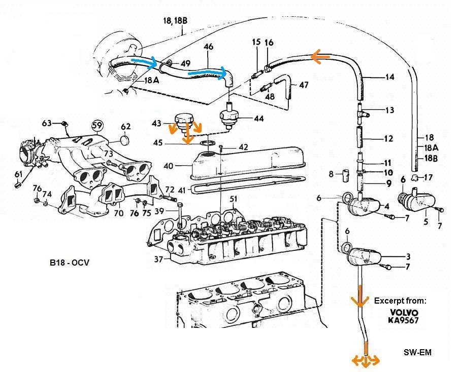
In the following excerpts of a factory diagrams, many of the components are shown for the various configurations, including some, like the B20A (single carb) which were not available in the USA. Shown are the common configurations.
In all of the following diagrams, Blue highlights Filtered Fresh Air and Orange indicates Crankcase Gases.
B18 OCV:
B18 PCV:
B20 (Carbs, single or dual):
B20 (F.I.):

--------------------------------------------------
External material sources are attributed. Otherwise, this article is Copyright © 2015-2026. Ronald Kwas. The term Volvo is used for reference only. I have no affiliation with this company other than to try to keep its' products working for me, help other enthusiasts do the same, and also present my highly opinionated results of the use of their products here. The information presented comes from my own experience and carefully considered opinion, and can be used (or not!), or ridiculed and laughed at, at the readers discretion. As with any recipe, your results may vary, and you are, and will always be, in charge of your own knuckles!
You are welcome to use the information here in good health, and for your own non-commercial purposes, but if you reprint or otherwise republish this article, you must give credit to the author or link back to the SwEm site as the source. If you don’t, you’re just a lazy, scum sucking plagiarist, and I hope your B18 ingests a brick! As always, if you can supply corrections, or additional objective information or experience, I will always consider it, and consider working it into the next revision of this article...along with likely the odd metaphor and probably wise-a** comment.
