Cooling System Notes
First published in Mar
2018 - R. Kwas, changes on-going [Comments Added]
The Cooling Systems of B18 and
B20 equipped vehicles, when in good working condition, has enough cooling
capacity, to handle the typical cooling requirements...but
this does require system to be filled with Coolant (not air!), and a good heat
rejection by the Radiator...so if the Cooling System is low on Coolant, or when stuck in slow moving traffic on a sweltering
hot day, when the hot outside air is moving through the Radiator only slowly, we
might want to keep an eye on the Temperature Gauge!
First things First:
Cooling System Rule No. 1:
Always use a 50% mix of ethylene glycol
"Anti-Freeze" and water in the Cooling System!...(Hereafter
also referred to as Coolant.) See also:
Galvanic
Corrosion in the Cooling System
--------------------------------------------------------------------------
Thermostat is in Charge!
Engine overheating and
TStat Replacement
Flow Routing of B18/20
Cooling System
Early Open Cooling
Systems (pre'67), vs, later, Sealed CS
Water Pump (WaPu)
WaPu Installation Tips
Other components
of the Cooling System Considered
Electric Cooling Fan
Getting-the-Easy-Stuff-Wrong-Department
Electric Cooling Fan Control
Bi-Directional Blade
vs. Sickle Blades Notes
Cooling System Additional
Fanbelt Tightening
Filling Cooling System
Heating / Defrost Systems
More
Defrost Air
Related Links
Reference Information
Bypass Thermostat
Thermostat action
Bourdon Tube
The Radiator (Pressure) Cap
"Closed" Cooling System
Late Cooling System
with Exp Tank
Auto-Burping
Early Cooling System
without Exp Tank
Early/Late Production
Expansion Tanks
Cooling System Operating
Pressure
Draining Cooling System
Flushing Cooling System
Heat Shedding of an
Automotive Radiator
Galvanic
Corrosion in the Cooling System
Thermal Sensing in the Cylinder Head
-----------------------------------------------

Figure 1.
Cooling System
Flow Diagram,
including the late production Closed Cooling System with Expansion Tank
change, is shown with "open" Thermostat and
Heater Control Valves to allow flow through both Radiator
("Outer Circuit") and Heater Core, respectively. What can be taken from this graphic, is that the
lower Radiator and return from HC hoses, should be cooler, the Coolant having
shed some its
heat in those heat exchangers.
Thermostat is in Charge!
Even if the Radiator were twice as big, it
wouldn’t help a bit if the controlling element doesn’t allow Coolant flow
through it...only when Coolant circulates through the Rad (AND air is
passing through that Rad), can Coolant shed its heat. The controlling element is the (not-so-lowly)
Thermostat. It has total
command of the engine Cooling System by virtue of the fact that it controls
Coolant flow through the Rad, so if CS circulation and Rad heat-shedding is in
order, it alone determines Cyl head and
Engine block
temperatures.
Link to
Thermostat Action
below.
Link to Info on Electric Cooling
Fan to help with airflow, below.
How does Radiator shed Coolant heat? Does it radiate? See:
Additional Information,
Explanation of heat shedding of an automotive Radiator.
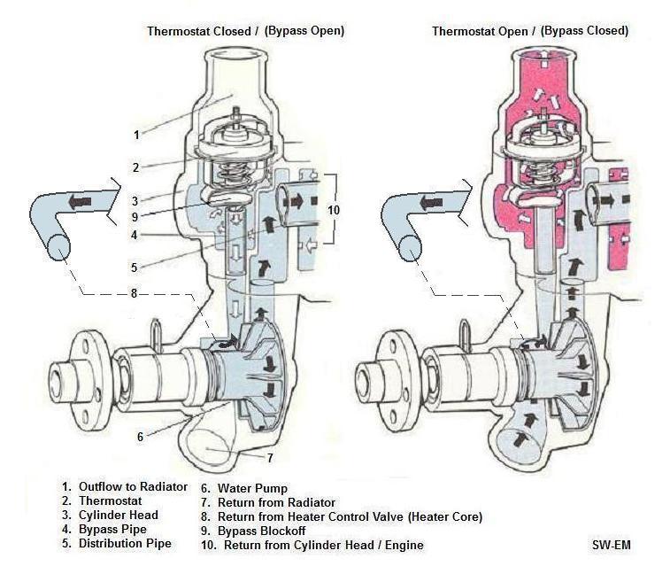
Figure 2.
Thermostat and Water(Coolant) Pump with Coolant flow detail.
Coolant returning to WaPu from Cyl Head is certainly warmed,
but shown as Blue before it
reaches TStat rated Temp. Once it reaches TStat Temp, it is shown in
Pink,
and TStat opens er... closes (see text!).
Pay the price! My advice
is to buy and install only first quality
Tstats from Volvo
or an OE brand-name supplier, such as Stant! The price is not going
to break the bank, and this is definitely NOT the place to save money by buying
an inexpensive part from automotive stores who also carry blue neon license plate
holders and magic products "guaranteed to give you 15% more horsepower" just by
adding them to you fuel or oil! (Does anyone actually believe such horse-puckey?) Refer to
Figure 2,
above and Reference Information:
Bypass Thermostat
below. The
inexpensive, standard, simple automotive Tstats they sell are not even the
correct part because they do not have the additional
blocking feature
for the Bypass Pipe(4).
This Bypass Block(9) deflector is an additional part to the standard Tstat,
somewhat unique to Volvo and some other European manufactured vehicles, allowing
the Tstat to not only control Coolant
flow to the Radiator, also called the "Outer Circuit" by
Volvo, during warm-up,
and while Tstat is closed, but it also routes Coolant to the
Bypass Pipe at the same time, allowing Coolant to circulate the "Inner
Circuit" for a faster warm-up. The Bypass in combination with the
Distribution Pipe(5) brings the head up to operating temps more
evenly, minimizing temperature differences and wear.
Link to
separate Tech Article:
http://www.sw-em.com/Coolant_Distribution_Pipe_Notes.htm .
Unlike simple Tstats, which simply block
(or allow) Coolant flow to Radiator, but which can allow hotspots within the
engine during warmup, the Bypass type Tstat works in conjunction with a Bypass Pipe
which allows continuous circulation
in what Volvo calls the the "Inner Circuit", while Tstat is still closed
and engine is warming. After opening,
Coolant is sent to the "Outer Circuit",
which includes the Radiator, where it can shed its heat, as with a simple Tstat, but additionally, Bypass Pipe
flow is blocked off at the same time,
stopping Inner Circuit flow. Although simple Tstats will fit, there 's a
real advantage to fitting the
Bypass Thermostat.
See also: Thermostat action
Engine Overheating and
TStat Replacement:
The first thing some owners do, is replace the TStat to cure an overheating engine...and this is
ok if the TStat is stuck closed, and actually the root-cause of the problem, but
more often then not, it is Cooling System effectiveness which is down (due to poor coolant
flow or level, or poor heat-shedding due to some other reason)...remember, the TStat
rating determines the engine operating temp, but it can ONLY do that if, cooling
capacity is available in the Radiator and the WaPu can get the Coolant there!
Installing a lower temp TStat will not cure an overheating engine if no further
cooling capacity is available...
First thing which should be checked when a hot engine is indicated, is the
Coolant level, second is the calibration of the Temp Gauge to be certain its
indication can be trusted... Replacing the TStat is often the first thing
tried when an overheating condition is indicated...I wonder how many TStats have been
wrongly replaced...
See also Related Links.
Flow Routing
of B18/20 Cooling System:
It can be seen that the terms "Closed" or "Open" Tstat really only apply to flow
through the Radiator...these terms ignore the state and function of flow through the Bypass
Pipe controlled by the Blockoff, and this is actually in the condition opposite
to the Rad flow.
The terms "Closed" or "Open" would best be replaced with "Circulating and Heating" OR "Circulating
and Cooling" because the circulation part never stops!
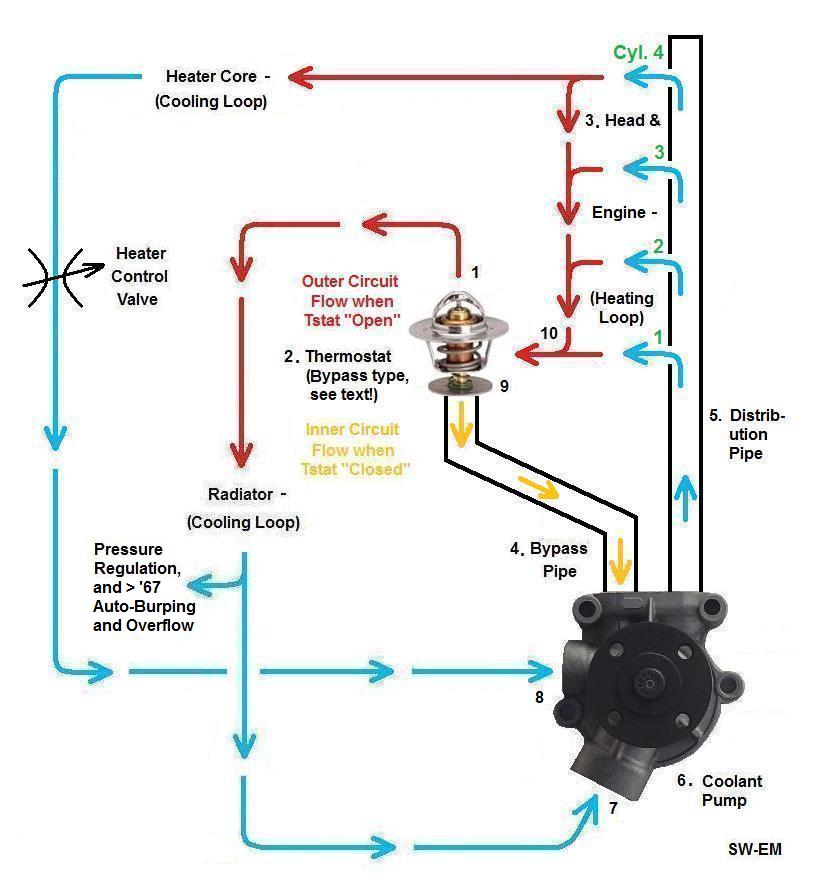
Figure 3. Identifier numbers correspond to those on
Figure 2.
Coolant Flow at Water Pump:
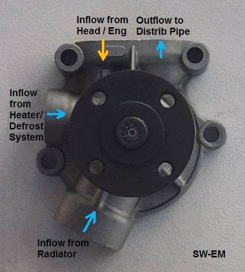
Figure 4.
B18/20 WaPu. Note: Three Inflows and only one Outflow!
Question:
Why an engine would need a
valve which restricts Coolant flow to the Rad at all, one might ask. Why not
just allow a free circulation of all the hot engine Coolant to the Rad?
Answer:..Because the Cooling System serves several important functions and
shouldn’t just be allowed to run fully open, at maximum cooling, which would
also allow temperatures to vary wildly! First is to allow the engine to come up
to temp where it can efficiently make power (a warming system really,
along with the Radiator blind fitted on
some vehicles in Nordic climates, [or the cardboard partial
Radiator block I add in January
in Connecticut!], the
second is to even out the temperatures of the various areas of the head
and block (when there are large temp differences, stresses would cause
accelerated wear or even cause cracks, etc.), and thirdly to make the engine
temperature constant over a wide range of operating conditions. This
also makes the point for always driving gently until the temp indicator is in
the normal range. Racing away immediately after cold starting makes about as much
sense as running a sprint immediately after getting out of bed! Finally, the
Cooling System sheds excess thermal energy...passenger compartment Heat and
Defrost are merely handy side uses for the excess BTUs available, to keep us
fragile humans in the comfy zone!
For the critical function of
controlling engine temperature, “china’s best” is still way less than
what I would ever consider acceptable for installation into any engine of mine
for this critical function!
As a matter of fact, as a rule, I can’t think of ANY
chinese trash products which I would knowingly install in any Volvo of
mine!...OK, maybe lamps...I think they have making those down fairly
well, and the jeopardy when they fail is reduced, but I’ll take and clean up a slightly greasy, and rusty
Swedish Steel bolt from my used stock,
any day, to a brand new shiny one from that “automotive” store where they
specialize in those impressive neon license plate holders! The only nice thing that
china trash hardware has going for it, is that if it’s too long, you can simply shorten it
(with a butter knife). See also:
Bolt Ratings
Tstat Inspection and Installation Tips:
Tstat is located right there, under the cast alloy housing connecting the top Rad hose on the top of the front of the cylinder head, where
one would expect it should be. If
you drain the Rad (Link to
Reference Information:
Cooling System Drains), even just partially, then loosen the two bolts holding it to
the head, and also the hose-clamp on the upper Rad hose, you can pivot the hose
and swing the entire hose and housing, with Tstat in place, to the side for
inspection. Remove the Tstat (sealed to the housing and Cylinder Head by a rubber edge seal) for
inspection or replacement. Note that there is no additional gasket between the
housing and head. You will also note that these are conspicuously absent from
gasket kits...this is for good reason...it doesn’t need one! Do not make and
install one, thinking that you are doing something good! The depth of the
step, in which the edge-seal of the Tstat sits, alone determines the
preload of that rubber seal. The step should therefore be cleaned of aluminum
oxide which forms (Link
to
Reference Information:
Galvanic Corrosion in the
Cooling System) before reassembly or installation of a new edge-seal, but
the design does not need to be and should not be changed by adding a
gasket!
Test of Tstat:
Check to see that Tstat starts to open at the temperature marked on it by
submerging in a pot of water on the stove and bringing the water up in
temperature. Use a reference thermometer in the water and suspend the Tstat in
the water to prevent conducted heat due to metal to metal contact with the pot
from affecting the test.
Low Coolant Level/Air in System:
The Coolant is what is used to
take the extra heat at engine and move it to the Rad, where it is exchanged
to outside air flowing through the Rad. A low Coolant level or excessive air in the
system keeps that from happening. Air in what is supposed to be the wet
part of the CS does not transfer heat well! Level
should be checked periodically (like during an oil change), and leaks need to be
investigated and remedied...they typically don’t get better or fix themselves!
No System Pressure:
Water boils at 212 deg
Fahrenheit at sea level air pressure...and without going into more science
than necessary, because the effectiveness of the Rad is better the
higher the temp difference between the air outside and the Coolant inside, it
stands to reason that increasing the Coolant operating temp
will make the Cooling System more effective. Let’s just say that the CS has to be
under a bit of pressure in order to work its best. The Pressure Cap allows
this (see
Reference Information:
The Radiator (Pressure) Cap) This raises the boiling
point of the Coolant in the system, and allows a more efficient exchange of heat
from the Rad. See also:
Explanation of
heat shedding of an automotive Radiator.
Early Open Cooling
Systems (pre'67), vs, later, Sealed CS. [This
title is due for a change as the terminology is confusing...in the meantime, see
also below for explanation of Terms Open and
Closed or Sealed!] The earlier systems were not equipped
with an Expansion Tank, and the Pressure Cap is located at the Rad
filler. (See also Reference Information:
The Radiator (Pressure) Cap),
and one will see a spring loaded inner sealing ring when
examining the Radcap underside. This ring seals against a mating seat inside the Radcap
fitting, and only opens when the pressure exceeds that which the spring is able
to hold back. When this pressure forces by the seat, it releases to the small
tube connected at the filler neck (but inside the outer sealing surface) and
which runs down the side of Rad and vents to the atmosphere (and ground). Since
the Rad is not full to the very top, there will likely only be air expelled out
this tube, but some Coolant loss can also occur (as a liquid, the Coolant is
non-compressible...it nonetheless still expands as it gets hot, compressing the
air in the top of Rad...not that big a deal here, but this is a notable
difference when compared to the:
Sealed Cooling System).
The increased boiling temp at
higher pressure is also the reason the Coolant may spew out of the Rad in a
scalding fountain when a Radcap is removed and the pressure is released, which
was keeping the Coolant from boiling. That’s why Pressure Caps have two
step
latches ...the first step releases the pressure (and may therefore
cause/allow
boiling), and the second step allows the cap to be removed. It's preferred
to let the system cool down a bit before opening it anyway...
CAUTION: Always open
the Pressure Cap of a hot Radiator
(or Overflow Bottle/Expansion Tank ) carefully, if you really need to, using the two step latches which
the caps have, and be ready for steam and/or boiling Coolant!
Other components
of the Cooling System Considered:
The
"Radiator Cap", allows the
Cooling System pressure to
build, but limits it to a maximum by opening to the venting/overflow tube to allow air
at top of Rad to escape. Reference:
The Radiator (Pressure) Cap
Expansion Tank. In about ’68 the
Cooling System on Volvos were
changed to a Sealed or Closed Cooling System with Expansion Tank. By adding an
Expansion Tank, and relocating the Radiator Pressure Cap
from the Rad filler
neck to this tank, Coolant could be allowed to expand into the tank. The tank gave an added benefit of “Auto-Burping” any
air out of the system.
Temperature (er...Pressure) Gauge: (LINK to separate Tech Article:
Temperature Gauge Notes) The temperature indicator used in 140 series
vehicles is electrical, requiring Ignition power. On vintage Volvos before
that, a filled thermal
system,
Bourdon Tube
(see: Reference Information: Bourdon
Tube below) indicator was used, and
this had the advantage of not needing ANY electrical power to indicated temp
(OK, at night, it needed the electrical instrument lighting to be seen, but it
would indicate just fine by moonlight too, trust me!). The Bourdon Tube
indicator is actually a sealed pressure sensing system, filled with ether, where
a sensor bulb in the head (actually just one end of the closed system) senses
the temperature by allowing the ether the expand from the temperature of the
Cylinder Head, then
indicating this on a sensitive pressure gauge located remotely at the dash. The dashboard gauge
and sensor are actually connected by means of a capillary tube. Since there is
a fixed relationship between temperature and pressure in this miniature sealed
system, the pressure gauge is
simply labeled in terms of temperature, and voila...the pressure gauge becomes a
temp gauge! Calibration marks are there if you look for them from below with a
light-source (LINK to calibration marks).
Checking Calibration of your Temp gauge:
Before one takes the indicated temperature of a vintage Volvo
(with its vintage gauge) too seriously, it’s always a good idea to check gauge
calibration. I recommend the Ronald Reagan “Evil Empire Principle” for dealing
with information from your temperature gauge: Trust but verify! The
simplest way is to remove the sender end from the head (being extremely gentle(!)
with the
vintage capillary tube...see:
Twisting
Off Temp Sending Bulb), put it into a Styrofoam cup, and add boiling hot
water. The needle should quickly move and point to the 100 Degree calibration mark. If
not exactly, it’s not a crisis, just make a mental note of where the needle
points, and one will still be accurately informed when the sensor is reinstalled in the
engine
again...unless you want to get intimate with the gauge mechanics and try to
adjust it (this is watchmaker level work and not really recommended for the
untrained and inexperienced). One could add a new reference mark at this
boiling point (this would of course be valid only for an unpressurized system.
Once
pressurized again, the boiling point of the system would be a
bit higher!.
LINK to: Checking
Temp Gauge Calibration
Water Pump (WaPu):
Sure, the manuals show the
rebuilding procedure, but I have yet to see anyone actually undertake this, and
I don’t even know if individual parts are (or were ever) available!
Replacement WaPus are not expensive. WaPus typically start to weep
as their internal shaft-seal gives up. Occasionally, a neglected WaPu will
self-disconnect the Coolant impeller from its shaft...the result is that
the fan makes contact with the Rad...it’s not a pretty sight when this
occurs...fortunately Rads are made of brass and can be soldered if not too badly
punctured. The trick is to catch a deteriorating WaPu before this
catastrophic failure mode and replace it. A simple check is to grab the
fanblades (engine off!...like one needs to specify this!!) and check the
WaPu shaft for slop (Radial and Axial), and it takes very little time to do this
during an oil-change. Any appreciable slop in either direction is an indication
that the WaPu is on the way out, and that a replacement should be procured and
installed at the next opportunity. Link to Thread:
Water pump query
(includes a video showing excessive slop):
http://www.volvoforums.org.uk/showthread.php?t=242031. If pump is not leaking yet, you’re lucky, but
the vibrations allowed by the slop will keep increasing until it does leak or
launches the shaft...it’s on borrowed time...so the question is: On what kind
of terms are you with Odin?!
Replacing a WaPu...this is a straightforward operation with few secrets,
but easily gotten wrong. It can be done
without removing Rad, I suppose, but that would make the job like
building a ship in a bottle, and totally unnecessarily!...Rad removal is so simple in any B18 or 20
equipped vehicles, and makes working on WaPu so much easier, that it is highly
recommended.
After removal of old WaPu,
clean all hose and mounting, and sealing surfaces well of gasket material and
sealer with a scraper and solvent...
WaPu Installation Tips:
Clean sealing ring surface of
head as well (this will take inspection with decent lighting from below or with a mirror, but is
important not to forget!). Pitting, which may be present to various extents,
must be cleaned so that it can be sealed with the gasket and gasket sealer to prevent incontinence upon first start!
It is easy and not uncommon for the
Sealing Rings which seal the WaPu housing to the
head, to get out of proper position due to the manipulation which the WaPu
undergoes before getting the bolts inserted and holding it into it final position.
This is a friendly Tip and Reminder to assure sealing rings do not get out of position as shown in the picture
following...also, to install correct ** Sealing
Rings
Proper installation technique is
NOT to thread in the securing bolts and use these to draw the WaPu into
position...this would surely result in sideloading the Sealing Rings...prepare all sealing surfaces by
cleaning, including contact area of the Cyl Head sealing rings, and
gasket, then applying gasket sealer, positioning
the WaPu (with neither pipe installed!) slightly below its final position, then
sliding it up to preload the O-Rings (NOT along the securing bolts!) , and
capturing the WaPu Housing in its final position with the securing bolts.
It is tricky as the gasket must also not to be allowed to get out of position during
the operation, plus everything is gooped up with gasket sealer at the time, so
patience and a sure hand is called for. Goal of the operation is to compress
the Cyl Head Sealing O-Rings and not mush them along sideways, which would surely
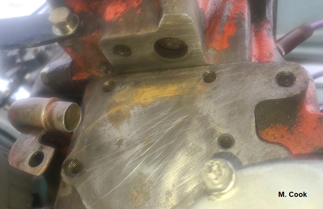
lead to this:
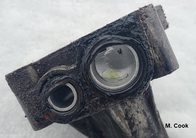
Unmistakable evidence of an improperly installed WaPu!
Here is what this owner found,
when investigating a Coolant leak. Sealing Rings are
out of place, having been sideloaded
during installation, so leakage was preprogrammed! Michael Cook pictures
used with his kind permission.
** Sealing Rings:
Short and tall (oval
cross-section) Sealing Rings, used to seal top WaPu
connection to the head above, are typically included with replacement WaPus.
They are compressed as a function of the headgasket thickness, so installer
needs to determine which ones to use based on the thickness of the headgasket.
The rule is simple: Thick headgasket: Use tall
sealing rings. Thin headgasket: Use short
sealing rings.
Reference Info for WaPu replacement:
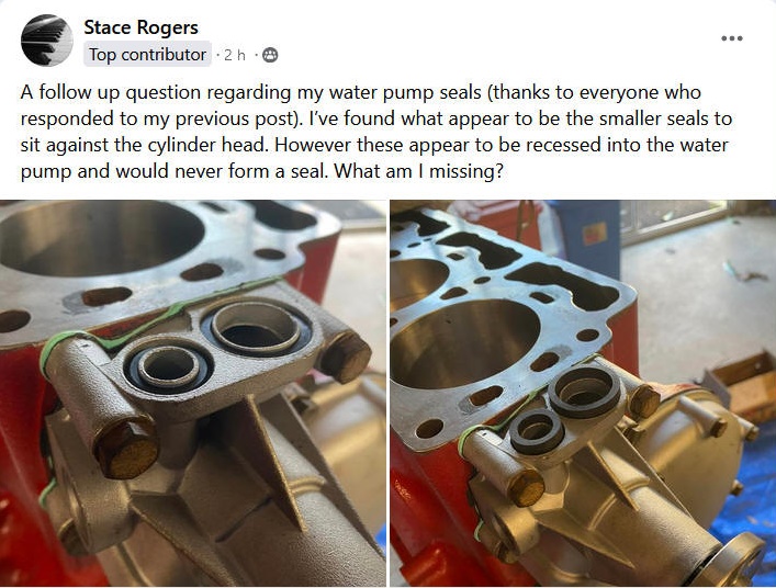
Stace Rogers picture used with his kind permission.
My response to this
 posting:
"Those are too short...and those are too tall...you need "The Goldilocks Seals"!
"
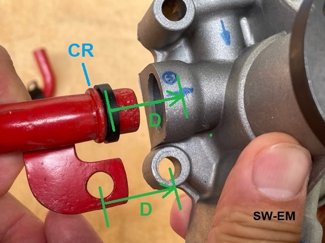
Sealing surfaces nicely cleaned and prepared for fitting a new WaPu, view
looking up under Cyl Head. Note the downward facing ports overhanging the
engine block, and the Heater/Defrost System return pipe on the left. Both
of these get their own Seals which are typically included with both the Cyl Head
gasket kit or replacement WaPus. They may not be interchanged!
-------
Once the WaPu is in place, the Heater Core and Radiator Return Pipes can be
installed with their (square cross-section) Sealing Rings.
See also separate Tech Article :
https://www.sw-em.com/B18-20_Heater_Core_Return_Pipe.htm
From the Often-Heard-about, yet-Seldom-Seen-Department:
Eroded Impeller: I’ve not experienced this myself on a Volvo WaPu, but “I’ve heard” that the fins on the impeller can actually dissolve away...then, the pump doesn’t work so good
and cooling obviously suffers. I have yet to get a Volvo WaPu, where this
has occurred, into my
little hands for a failure analysis, but I know that the OE pump impellers are
made of light Aluminum alloys (Reference:
https://en.wikipedia.org/wiki/Aluminium_alloy ), so the erosion may be explained by the fact that the
impeller became the anode in the galvanic connection of block (iron cathode) to
WaPu (with the Coolant acting as the electrolyte), and just dissolved away...one
molecule at a time. Reference:
Galvanic Corrosion in the
Cooling System.
I rather doubt WaPu spins fast enough to cause erosion
by
Hydrodynamic Cavitation.
I haven’t confirmed my galvanic reduction idea, but it is a theory of mine, that
those impeller failures could have been caused by using plain water in the
system, which doesn’t contain anti-corrosives the commercial Coolants do.
Besides lowering the freezing point of the Coolant, this makes the point from an
anti-corrosion standpoint, of always using a 50% mix of ethylene glycol
"anti-freeze" and water (preferably deionized) to fill the Cooling
System! Reference:
Cooling System Rule No. 1! If the reader can supply some pictures of an
example of an eroded Volvo impeller, and associated information on the circumstances
which caused it, for inclusion here, I’d love to see them...please
contact the author! Here is the best and only picture of an eroded
Volvo Impeller our crack research team (Gargle Images) was able to locate:
LINK: Eroded Volvo WaPu
Impeller.
Changes and Modifications to Cooling System:
One of the simplest and most worthwhile modifications which can be made to the
pre '66 systems is the upgrade to a sealed/pressurized system with Expansion
Tank, similar to
the later factory version. Link to:
Reference Information:
The Closed Cooling System.
This is an
inexpensive modification which has multiple advantages of preventing Coolant
loss, Auto-Burping minor amounts of air from the system, and allowing simple visual inspection of
Coolant level.
LINK to: Service Notes Page:
Cooling System.
Link to Engine Pre-Heaters
used in extremely cold climates (See also: SW-EM Accessories Page):
http://www.sw-em.com/accessorize.htm#Engine_Block_(Pre-)heater
-------------------
Coolant Distribution Pipe:
As seen above the Coolant Distribution Pipe (Item 6
above) routes Coolant from the WaPu to Cylinder Head and Engine Block equally.
This pipe assures equal distribution of Coolant, and that Cylinders furthest
from the WaPu are not "at a disadvantage".
Link to separate Page:
Coolant Distribution Pipe Notes
-------------------
Adding an Electric Cooling Fan (ECF)...is
a popular modification, since it helps assure a decent airflow through Rad during even slow roadspeeds, when RPMs, which rotate the less-than-impressive OE fans, are
also down, and this allows Engine temperatures to climb to, in some cases, alarming levels. An
electrical fan is automatically controlled by a Temperature Sensing
Switch, (for discussion of the location of this switch,
see also below!), such that even during slow engine/roadspeeds, when system heats up
because Rad is not able to shed heat, the electric fan is powered to help out by moving
additional air. Although I don't recommend installing an ECF and adding
its significant load (10Amps or higher are typical) to an OE Generator based
Charging System, the benefits of cooling improvement easily outweigh the
additional electrical load/burden of an ECF on an
Alternator equipped Charging System, and they are well within its output
reserves! The electrical fan can even be discretely mounted in
front of Rad in a Pusher Configuration with OE fan left in place for an
relatively unchanged engine compartment appearance (if one overlooks the Alternator,
and
Temp Sensor!).
Each installation is different
when retrofitting,
so which configuration is used is really up to the installer and the actual ECF
to be installed. As far as...”What’s better: Pusher or Puller ECF?” ...I don’t think the Rad much
cares what makes the airflow, but locating a Pusher ECF in front of the Rad
allows the engine compartment to stay relatively unchanged as previously
mentioned...when the ECF is not
called for and unpowered, air still passes
easily through its blades and
onto the Rad freely and unimpeded.
Pusher ECFs are often part of an assembly with an air directing shroud,
which optimizes the airflow and prevents air from bypassing the Rad. These
should be retained when installing if fit allows, to increase the effectiveness of airflow. (see
Figure 5)
Correct Polarity and resulting direction of Rotation and airflow
need to also be determined when connecting up an ECF. See also
Bi-Directional Blade
vs. Sickle Blades Notes
below. A quick
test-connection to power can be used to determine direction of rotation and airflow
(as a DC motor, polarity does matter, and when this DC motor is turning a
fan, it determines the direction of airflow! (...from the
Getting-the-Easy-Stuff-Wrong-Department: LINK to Getting
airflow direction of ECF wrong!
http://www.brickboard.com/RWD/volvo/1370797/120-130/puller_fan_850v70_130.html ).
As a general rule, when mounting the electric fan assembly, any actual contact
to the Rad, if unavoidable, should be assured to be soft and protected, to protect the thin Rad
material from vibration wear.
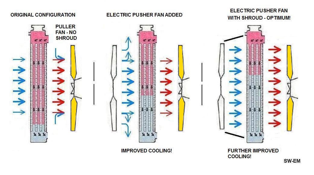
Figure 5. Showing
original non-optimized Puller Fan, an electric Pusher Fan added, still allowing
bypass, and finally an optimized additional Pusher Fan with Shroud to assure low
bypass. Volvo recognized the performance advantages of the Shroud
also, so later models had this optimizing feature around the oe Puller Fan on the
WaPu.
Electric Cooling Fan Control: There has been some discussion on
location of Temperature Sensor for Elec Cooling Fan ...my recommendation is to
locate Sensor to monitor Coolant temp at the output side of Rad...so at the
bottom! In this way, the ECF will be able to augment Rad heat-shedding when Rad
output temp rises such as during hi load, or slow travel and accompanying poor
airflow through Rad. With Thermostat open, and Sensor mounted at upper hose,
Sensor would always see a hot condition (and ECF would be
ON continuously, maybe
needlessly) since Coolant coming from engine will always be hot!
Here, a very nice implementation of a Temp Sensor in the Rad Return Pipe.
A discrete location, perfectly reversible, and right where it needs to be!
Michael K. picture used with his kind permission.
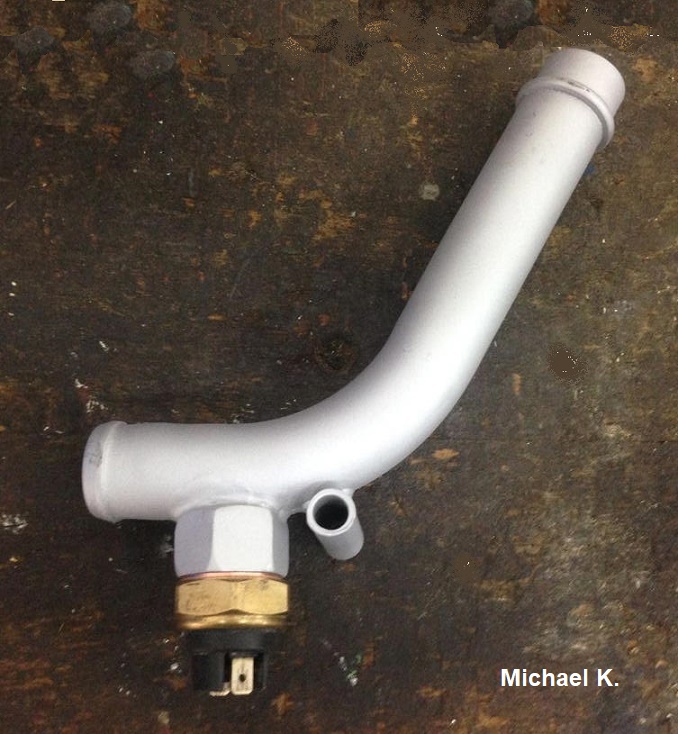
B18/20 Radiator Return Pipe modified with Coolant Temp Sensor.
Idea is to sense if Coolant is returning from
Radiator insufficiently cooled, and turn ON ECF to improve cooling effectiveness
of Radiator when necessary. Sensor could be adjustable to allow
characterizing the system and selecting an appropriate turn-ON point (like when
Temp gauge needle approaches the Red!), but once that is set,
it shouldn't be necessary to have to mess with it too often. I'd suggest a
92-95şC rating.
Link to:
http://www.sw-em.com/temperature_gauge_notes.htm#overheating_vehicle___are_you_sure
Controlling the significant fan current by
means of a relay is a lot easier on the contacts of the Temperature Sensing
Switch (TSS), and is highly recommended if the sensing switch is expected to
last longer than one oil-change interval. See Figure 6. for suggested circuit.
Electric fan should be powered by Battery Power, such that it can continue to
cool Rad after parking when thermo-siphoning continues (and the additional air moving through engine compartment
will also serve to decrease general heatsoak...not such a bad thing!). As an option, a manual
control on
dashboard gives the driver additional
manual control (and ability to anticipate needing additional Rad airflow,
like when coming to a hill or approaching slow moving traffic...Temp Sensor
control can only react after Rad is already hot!), but Manual Control is enabled only during Ignition power ON,
to prevent a discharged Battery, if forgotten...
ECF Circuit Function: The suggested circuit shown below uses a relay (5
terminal type is shown, but a 4 Terminal relay type would work fine for the ECF
control, Reference:
Comparing 3,
4, and 5 Terminal Relays
) controlled by a Temperature Sensing Switch .
(Fused) Battery Power is used to supply ECF Relay ...and can be taken from
the Fuse4 loads side (two Black Wires!), on a 122 for instance (increase Fuse
current rating to 20A to accommodate the high ECF current [Wire Gauge is
adequate for ECF current up to 10A but no more...if ECF current is measured at
more, existing wiring should not be used, but a heavier gauge wire should be
added from Ignition Switch Term 30, and by way of a separate fuse to power the ECF
circuit!]). [Author also highly recommends
against adding this significant current
load to the terrible Lucas automotive aberration
Fuseblock of a P1800 without first replacing it with a reworked one...you
have been warned! See also:
SwEm
Technical Bulletin Number 3
]
Powering the ECF with Battery Power allows cooling of the Rad to
continue even after shutting OFF engine. The TSS automates the shut-off to
prevent a drained Bat. IGNition Power should be used when including the Manual
Switch Option (...and this can be taken from the Fuse2 loads side on a 122 for
instance), this gives driver additional manual control, but only when IGNition
is ON and Charging System can supply power (this also prevents an inadvertent
drained Bat which would occur if the switch was powered by Bat, and was left ON
after parking and shutting OFF engine [and Charging System]). *
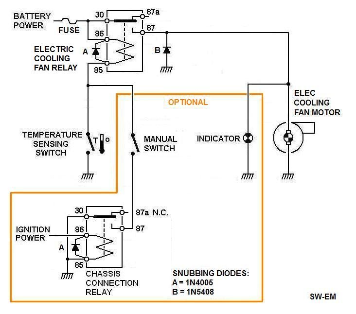
Figure 6.
Circuit for retrofitting an Electric Cooling Fan. Temp sensor activates
Fan Control Relay, which supplies ECF with Battery Power.
Optional Manual Switch and
Indicator are shown added. Chassis Conn. Relay only
allows manually activating ECF during engine (Ignition) ON, so prevents a dead Bat if driver
were to forget to turn OFF Manual Switch after parking. Automatic control
remains functional at all times. Fusing
the Battery Power supplying this circuit, is good practice.
For Fuse value, measure
Steady State Motor current and double that value for the Fuse. (Reference:
Fusing
Rules.) Two ratings of Snubbing diodes are shown,
A
type for low Relay coil current, B type for High Load current. or B
type could be used in all three circuit locations. See also below!
Notice in the above circuit, that Either TSS OR Manual Switch can
activate the ECF Relay...yes its an OR-ing circuit, but there are no ORing
Diodes included...how come? See:
http://www.sw-em.com/OR-ing%20Circuit%20Notes.htm An OR-ing Diode and
a Snubbing Diode may be the same component, but they are used in very different
ways. See also:
https://en.wikipedia.org/wiki/Flyback_diode
Bi-Directional
Blade vs. Sickle Blades Notes:
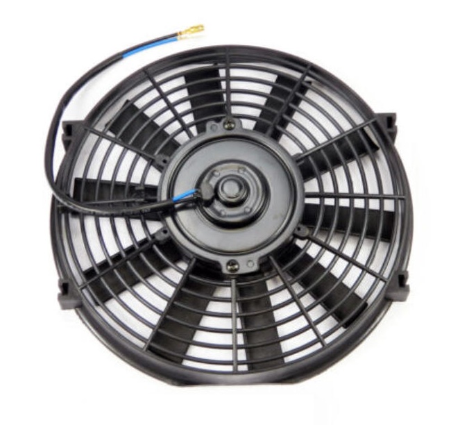
Bi-Directional Blade Electric Cooling Fan.
On fan with straight blades, the blades have no preferential direction of
rotation, so by simply reversing the DC supply to the motor, air-flow direction
is reversed. If the frame has a preferred mounting side, it is simply a
matter of trying either polarity to see which gives the air-flow direction
through the Radiator, then making that polarity the permanent one for service.
The specified current draw for this straight bladed motor is calculated from the
80W at 6.7A (design for a 50-100% increase over that at startup).
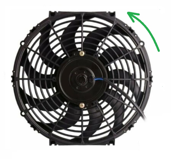
Sickle Blade Electric Cooling Fan.
Preferred direction of rotation in Green.
Sickle style blades have a preferred direction of rotation! These are more
efficient in that direction (the root of blade cuts the air first, and tapered
end of blades gives the least turbulent transition for air departing blade end).
This also makes the design less noisy. Because of this preferred direction
of airflow, and possible preferred direction of rotation of the motor, air-flow
direction (polarity of motor energization vs. mounting) should be checked and
established before mounting, or else you might get it wrong, like the poor guy
above. Link
The current is specified for the sickle bladed motor: 12.7A
Note also that both ECFs are within and quite close to the side of their
housings. This design approaches a more efficient
ducted fan design
configuration.
Both ECF pictures were "harvested" from some epay offers.
-----------------------
Cooling System Additional:
Fanbelt Tightening:
Fan Pulley Failure: Reference
e-mail from Gert: gav.ta at hetnet.nl
Picture of broken pulley by Gert...lesson here is:
DONT OVERTIGHTEN FANBELT! [...of
course, too loose is not good either...See: Overheating Amazon
under
Related Links below!]
http://www.brickboard.com/RWD/volvo/1571490/120-130/waterpump_pulley.html

Figure 7.
Fatigued WaPu Pulley (of formed Sheetmetal)
...an over-tightened belt can contribute to this disaster!
-----------------------
Temp Gauge:
Filled thermal system
temperature gauge: Bourdon tube pressure gauge.
Link also to separate Tech
Article:
Temperature Gauge Notes
Normal action of the
Temperature gauge: Since the Temp gauge is direct reading and undampened, the
observant driver might very well notice some movement of the temp needle,
particularly for the first opening of the Tstat. This is absolutely normal and not an
indication of a problem!
-----------------------
Wetter Water, Surfactants (and other Snake Oil): These are additives to
Coolant which decrease the
Coolant surface tension and assure good wetting of the head and block, and in
this way purport to allow a "better thermal transfer"... I have no experience
with these products because I have never really seen much need to improve
thermal transfer in my Cooling Systems...whenever I’ve looked the inside of the
cooling jacket of a head or block, it looked like the Coolant was having no
problem wetting the surfaces, and while I don’t doubt the fact that surfactants
reduce surface tension...I do question what advantage they give in my vintage
Volvo, and I further bet a Hot-Fudge-Sundae that they’re just not necessary! I
think that most Cooling System issues can be corrected with a good flushing and
burping of air from the system.
-----------------------------------
Fanblade Fatigue Failure Advisory:
Several fans types and styles were used in production. From a one-piece
two-blade design on the B16, which move about as much air at idle
or at any other speed for that matter, as a 6 year old
blowing out his birthday cake candles...(I guess they didn’t design their cars to stand
still!), to plastic or Stainless five blade designs, viscous coupling driven
(which limits their speed), and flexy blades (which vary their blade-bite
according to RPM), fitted in conjunction with an air-flow efficiency improving
shroud found on late B20s.
A recall
was issued in the early seventies to replace the one-piece, four bladed type,
which could separate due to material fatigue. This resulted in launching a
separated blade under the hood...where it would go, and how much damage it would
cause, is again between you and Odin, but generally governed by “Dat law of
de Murphy’s” [Dutch version, in case the reader's wondering!]
---------------------------------
Filling
Cooling System:
Complete filling is important, because air in the system doesn’t transfer heat
nearly as well as Coolant, and a Tstat surrounded by air might not even open at all
for the same reason - even though the engine may be cooking hot! Remember: It
is (supposed to be) a liquid-cooled engine! When the Cooling System has been
drained, and needs to be refilled, following a bit of a procedure for refilling
will assure good results and function. On the earlier systems without Expansion Tanks,
this is straightforward, but a couple more steps are required in the case of
the later systems where an Expansion Tank is fitted.
Reminder: Use extreme care when working around
MOVING
and HOT engine parts!
The fingers you can burn (or loose!)
might be some of your Les Paul tickling favorites!
|
Start Here! |
Open System |
Sealed System |
|
1. Close and snug
all drains (at engine next to
oil filter, and on bottom of Rad) Fill
system with 50% mix. Squeeze top and bottom Rad hoses to help burp
out trapped air. Volume required is 1 to 1.5Gallons, depending on
state of fill of Heater Core. |
|
|
2. Start engine
with Radcap removed, and heater temp control valve set to warmest
position. Allow engine to idle while checking for leaks around
hose-ends, WaPu, and drains. Monitor Temp Gauge. |
|
|
3. When Tstat
opens (and Temp Gauge falls for the first time), refill Rad to
full, as Coolant level drops. Check for warm air from heater or
defroster. |
|
|
4. Squeeze top and
bottom Rad hoses again to agitate Coolant, and manually burp out any trapped air.
This also assures Coolant is in good contact with Tstat. |
|
|
With engine still
running, continue at right! ▬► |
System with No
Expansion
Tank |
System with
Expansion
Tank
|
|
|
5. Fill to one
inch below Rad Filler Neck, leaving an airspace above fill
level.
Replace Rad cap |
5. Fill to
absolutely full (just below overflow pipe junction). Replace Radcap.
Raise Exp Tank to above Rad level. Fill Exp Tank midway, allowing
air to bubble out. When there are no more bubbles, replace Exp Tank
in its holder. |
|
|
|
|
|
After engine is OFF
and allowed to cool, check and top up level to one inch below Rad
Filler Neck. |
|
|
|
|
Check level at Rad,
top up to one inch below Radiator Filler Neck as necessary. Replace Rad cap. |
Level at translucent Exp Tank
should be between Min and Max markings. Top up to midway in normal zone as
necessary, replace Exp Tank cap.
Monitor level at
Exp Tank when cold after next several engine hot-cold cycles, and
top up to midway in normal zone as level drops due to
Auto-Burping.
|
|
|
|
|
Figure 8.
Procedure for filling Cooling Systems.
My response to a Brickboard Thread: Burping New
Radiator, (
https://www.brickboard.com/RWD/volvo/1684763/444-544/burping_new_radiator.html
) for how to fill a Cooling Sys with new Rad):
"I'd recommend keeping the Rad Cap of a newly filled Cooling System open (with
Temp Control on hot to also open Heat/Defrost Loop) until at least the first
TStat opening so you can monitor and top up after the level falls, as air moves
out...your temp "shooting up" was caused by a big bubble(s) of air which allowed
hotspots (possibly local boiling) and which need to be replaced by Coolant...I'd
fill Rad and pump on the hoses by squeezing even before starting the
engine...and after starting also (CAUTIOUSLY, keeping bodyparts from moving
engine parts!), by covering Rad with palm and again squeezing top hose and
adding some shock and turbulence into the Coolant path for the purpose of
dislodging air-bubbles.
"started pushing fluid out of the radiator top cap." ...this does not sound
right! In a CS with Exp Tank the Rad cap is strictly a sealing cap, so NO
Coolant should EVER even be able to come out here!...the Pressure (and overflow)
is regulated, and allowed by[, in]
a CS with ET, by the Pressure Cap which is now located on the Exp Tank. See
also: https://www.sw-em.com/Cooling_System.htm#closed_cooling_system
Only after the majority of air is removed from the CS by letting engine run
while Rad is open (and no pressure can build), and we monitor and manually burp
and top up CS, and no more drop in the Coolant level is observed, should the Rad
be sealed with its (Sealing) Cap, and Pressure Cap also can seal the CS on the
ET (filled to Min level)...only then is the Auto-burp (Step 2 in graphic) able
to handle what little air is left...before that, it would be completely
overwhelmed by all the air (and that is what caused your overflow!).
I would say this info applies to B18/20 as well as B16 CSs. "
--------------------
Heater
Control Valve (HCV)
Original equipment HCV are quality
components, but
after 50 years, they can develop leaks as the rubber parts have aged...who can blame them? VW valves reportedly will fit and are not
quite as expensive. OE replacement valves are available but not exactly inexpensive.
Rebuilding is an option but is a significant undertaking.
Note that during HCV removal, not to overlook the filled thermal system
sensor bulb (not unlike the Temperature
sensing and indicating system) which monitors heater air box and adjusts valve, thereby
further adjusting Coolant flow
through Heater Core (HC) to maintain a constant temperature
in the heater core enclosure.
Link to separate SW-EM Tech Article:
Heater Control Valve.
--------------------
The Heating / Defrost Systems of 122 and
1800 are similar, but there are differences, most notably in the HC outlet
location, hoses, and HCV configuration. Both 122 and 1800 have temp
sensing bulbs in the air-box (not shown below), which feeds this back to HCV and
so allows a closed loop temperature control. See SW-EM Tech Article:
Heater Control Valve
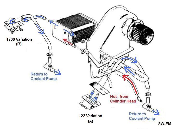
Figure 9.
Coolant flow at Heater Core and
Heater Control Valve.
122 and 1800 Variations
(HC input from Cyl Head uses same hose, but other two, connected to HCVs are
different from 122 to 1800!).
My answers to questions on Coolant routing:
(Thread: Heater Core & Heater Valve - which comes first?
http://www.volvoforums.org.uk/showthread.php?t=262572 )
(Coolant flow through HC and HCV...does it
matter which comes first?)... "...is a
series circuit, so from the point of flow, it does not, and as you've
previously also pointed out, the only major difference is that if Heater Core
comes first in flow-path, Heater Control Valve would be subjected to the cooled
Coolant, possibly being a bit gentler on that component (...but I doubt this
really matters...it's certainly not critical, since HVC does come first in other
models and vehicles). I guess what I'm saying is, I would change hoses at your
next convenience (not pull over in a panic-stop and feel you must do it before
driving another foot)...it's just not critical!
If using the preformed OE hoses to make these connections, they do have a
preferred placement."
...not to forget my 444/544 driving friends:
My response to a thread (
https://www.brickboard.com/RWD/volvo/1642544/444-544/heater_core.html
), where owner states: "...water doesn't circulate to the core from the
pump, the heater core hoses never get hot..."
Info/Comments not part of original post
highlighted.
"I'm no expert on B16s
(see pictures below for B4/B16 info!), but pipe running from Wapu to back of B18 engine is the RETURN from Heater Core, by way of HCV...
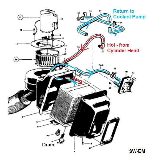
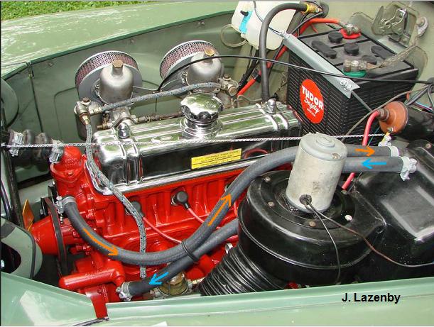
Figure 10.
Coolant flow in a B18 equipped 544.
Hot supply is from stubby,
90ş pipe at back of Cyl Head, so
if you're getting no flow at Heater Core, it's likely the Heater Control Valve
is not allowing flow....but first, check Coolant level and assure it is
adequate. Next, "open" HCV (set
Temp at control to Hot) and feel hose temp on either side to confirm
flow. HCV and HC are plumbed in series, so any blockage in that path will
prevent flow (To repeat and emphasize: ANY blockage in that
path...including of plumbing, HC or HCV!). Check and verify movement
action of Temp control cable is really getting to HCV (sheath is not slipping,
allowing lost motion at HCV control , as is known can
also happen at the Choke Bowden
Cable)."
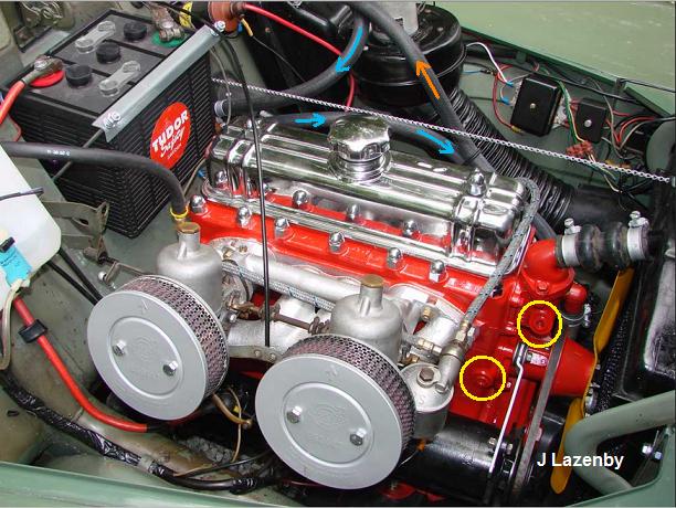
The 444 can also have a B4 or B16, for which heater hose
routing is similar. Pictures of a really clean engine compartment supplied
by, and used with the kind permission of, Joe Lazenby.
 |
 |
|
Orange is hot into
Heater Core. Blue is
out of HC and back to Cooling Sys manifold, by way of Heater Control
Valve. |
View of the Heater hoses from from the other engine
side. Note also two additional fittings at
yellow into Cooling
System. Shown plugged, these fitting are where optional
Engine
Pre-Heaters, or Cabin Heaters may be plumbed into system.
|
--------------------
More
Defrost Air at the Cost of the Rear-seat Passenger's Footwarmth!.
We vintage Volvo drivers have always loved our
very effective Heating/Defrost systems, sized to keep us comfy in regions above the Arctic Circle
(like half of Sweden!)...or Minnesota!...but if you’ve ever felt like you could use a bit more Defrost
Air than your Amazon or PV was giving, or use it sooner, this simple little trick may be of interest to you.
As can be
seen in the reference diagrams of Air Flow controls and the Air Flow diagram from
Owners Manual
below, ducting of
the rear-seat passenger floor-vent is in parallel with the Defrost
ducting.
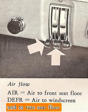
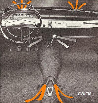
Figure 11A, 11B.
Heat (Gray) and Defrost Air (Orange) ducting.
Pic Source: Amazon Owners Manual
This means that when in the
Defrost position, that rear floorvent is dumping precious warm air, which might
be
better used clearing the windows, onto the rear floor, even when there may be
no occupants to benefit from it...so if there is no one riding in the back who needs
their tootsies toasted, a simple SpongeBill Foamplug (long-lost
relative of the
beloved TV and film-star shown below, with possibly his cousins) inserted into each of these two vents just ahead of
the central seat-belt loop, will instantly and painlessly, make a lot more Defrost Air available at
the windshield. Simple!

Figure 12.
SpongeBob with cousins...
(...and may Greetings, Thanks and Salutations be upon the man who invented the
Wonder-Bra!).
--------------------------------------------------------
Related
Links:
http://www.sw-em.com/temperature_gauge_notes.htm
http://www.sw-em.com/Coolant_Distribution_Pipe_Notes.htm
https://www.sw-em.com/accessorize.htm#Engine_Block_(Pre-)heater
Cooling System threads:
Overheating Amazon:
https://forums.swedespeed.com/showthread.php?587435-Overheating-Amazon
[In this case, after doing just about
anything and everything one can name to cure an overheating Amazon, including
replacing the WaPu, the last root-cause of overheating after a long-distance
highway drive seems to have been: "fan
belt was extra loose"...which
shows that the simple and obvious items should always be checked first.
Note also that the oem (Front and Rear) Generator Mount Pivots often vibrate
loose, which causes them to wear the holes oval in the bracket, with the final
result being a loose Fan-Belt. A loose and slipping Fan-Belt cannot
effectively turn WaPu to move Coolant!...or provide mechanical input to the Charging System.
]
http://www.sw-em.com/temperature_gauge_notes.htm#overheating_vehicle___are_you_sure
http://www.brickboard.com/RWD/volvo/1298448/120-130/cooling_system_problem.html
http://www.brickboard.com/RWD/volvo/1357358/120-130/temp_gauge_problems.html
http://www.brickboard.com/RWD/volvo/1109542/120-130/reconnecting_temperature_gauge_sensor_wire_electric.html
---------------------------------------------------
Reference Information:
Bypass Thermostat:
From:
http://www.stant.com/index.php/english/products/consumer-products/Thermostats/abcs-Thermostats/
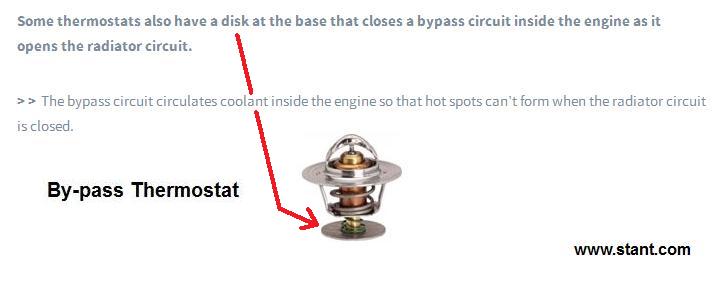
Figure 13.
While Stant By-pass Tstats have a disc, other manufacturers, like the one shown in
Figure 2. above,
have a U shaped Bypass Blockoff...function is the same: To allow or
block flow into the Bypass Pipe.,.
Thermostat action: As Main Valve
opens (moves down to allow flow to Rad) and By-Pass Valve also moves down to
block flow into By-Pass Pipe.
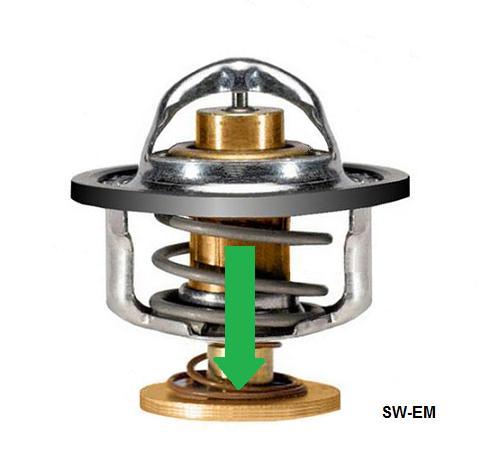
Figure 14.
Bourdon Tube:
PLACEHOLDER
Link to a popular reference
site:
https://en.wikipedia.org/wiki/Pressure_measurement#Bourdon
The Radiator (Pressure) Cap:
Once again, there's a lot more happening in this deceptively simple part, than
immediately obvious! The cap allows pressurization and limits and
regulates the pressure
of the Cooling System as it heats up, but also allows outside air
back into the system when
it cools
down.
(See also: Cooling System
Operating Pressure, below)
The following graphic shows operating conditions at the
Pressure Cap for an Open Cooling System. With a Closed
System, the Radiator Pressure cap is a simple
Radiator (Sealed) Cap (see below) and the Pressure cap is relocated to
top of Expansion Tank, but action is substantially the same, shown
at:
Closed Cooling System Operating Conditions below!).
Remember...filling the ET of the sealed system only, will not
necessarily fill
Radiator if siphon has been broken...so if more than about a quart of Coolant
has been drained from system, or if ET is
empty, or if system has boiled over, and one is just not sure of state of fill, Sealed Cap should be opened and Rad
checked and filled separately!

Figure 15.
Cooling System action and conditions at Pressure Cap. Pressure Cap
is located at Radiator in the older Cooling System without Expansion Bottle, or
on Expansion Bottle on later Cooling Systems. Both are really "sealed" by the
Pressure Cap, the advantage of the later system with Expansion Tank is that
there is more volume available in the Exp Tank to accommodate normal Coolant
expansion, and even a limited amount of boiling without loosing too much
Coolant.
Open Cooling System Operating Conditions:
Condition 1. Cold and stable condition (no pressure difference
between CS and outside). Coolant is at ambient, no pressure in CS.
Pressure seal is closed as spring holds Pressure Valve closed against
seat. Vacuum Valve is also held closed by its spring.
Condition 2. Coolant expands and pressurizes CS as system warms.
Coolant expands into airspace above fill level, and Pressure Spring releases air above
Coolant and allows but limits pressurization
to rated value. .
Condition 3. Cool down after engine shut-off. As CS
cools and Coolant contracts, Vacuum Valve allows outside air in to equalize
pressures and return system to Condition 1.
Condition 4. "Boiling Over!" As bubbles in
the CS, due to boiling Coolant, raise level further, Pressure Spring may also
allow Coolant to escape. Coolant overflows and is released and lost.
The Radiator (Sealed) Cap: If there is an Expansion Tank fitted,
the Radiator Cap is a truly simple Sealed Cap which simply closes the filler. [Unless it
was previously a Pressure Cap whose pressure equalizing function has been "defeated and altered" by
the owner...see below.
Modifying an older Cooling System without Expansion Tank, into a newer
Cooling System
with Expansion Tank:
Link to SW-EM Service Notes on
modifying a Cooling System into a Sealed Cooling System.

Figure 16. Early
Radiator Filler with RadCap removed,
showing Outer Sealing Surface at A, Inner (Pressure) Sealing Surface at
B.
Visible is also a (Blue) wire which is part of the
simple
upgrade to a Closed CS, and
which intentionally holds the Pressure Seal open, turning what was a Pressure
Cap into simple Sealed Cap. When making this
modification, the Vacuum Seal of Pressure Cap should also be defeated so that outside air is not
drawn in at Radiator during Coolant contraction (Condition 3), as this would
defeat
Auto-Burping...see below.
Make-up air should be allowed to be drawn in Pressure Cap located on Expansion
Tank.
-------------
The "Closed" Cooling System:
Some explanation is called for here, because the terminology is confusing,
possibly again caused by quirks in Swedish to English translation!
Although the late CS is called "closed" in the Volvo Workshop Bulleting
below, it shouldn't be interpreted to mean that the early system was "open"!
Before addition of the Expansion Tank, the CS is certainly also "closed"...it
must be in order to make pressure which allows it to be more effective. So
what is the difference between the CS without and with ET?...not much actually,
other than location of the Pressure Cap, and ability to visually check the
Coolant level with just a glance at the translucent ET. Before adding the
ET, such a quick visual check was not possible...and the Pressure Cap would need
to be removed from the Rad to allow checking the level inside... The other
advantage to the late CS with ET is that if overheating was to occur, the ET
could capture more of the Coolant, which in the CS without, would be
irretrievably lost onto the ground.
The configurations of CS should
simply be called: Early CS, without Exp Tank, OR: Late CS,
with Exp Tank. To call the Cooling System, for instance as here in the
Service Bulleting "Closed" is Confusing. One can easily think the earlier
systems were "Open", but this is simply not the case!
Excerpt from Service Bulletin 1966 P25, 5. Source:
http://volvo1800pictures.com/wb/2/2_htm/26-05%20April%201966%20Closed%20cooling%20system%20P1800.htm
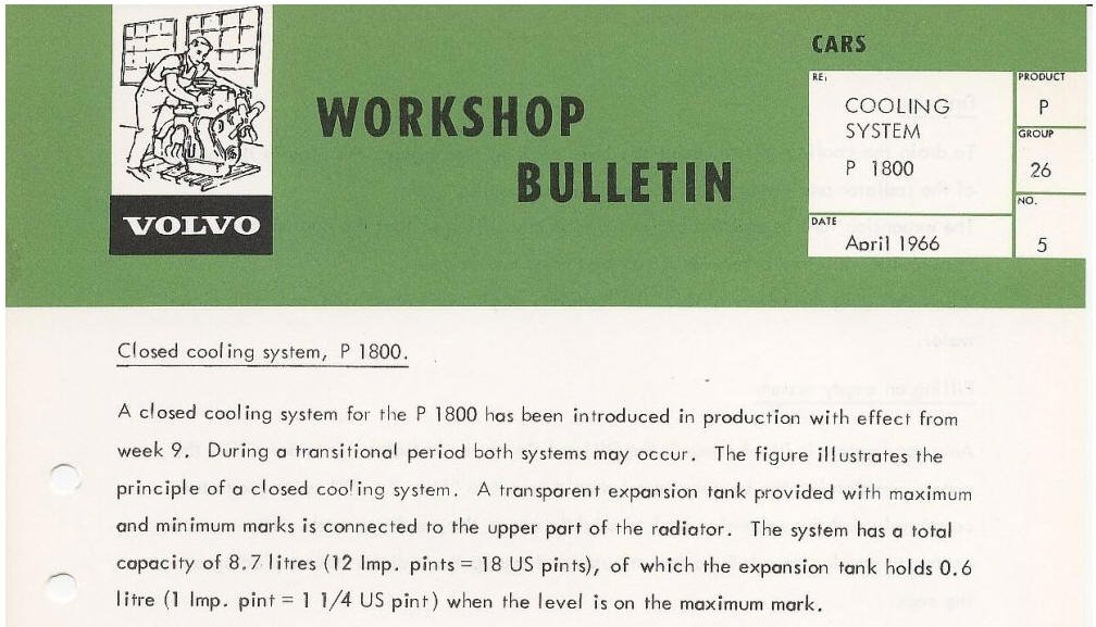
Figure 17.
Late Cooling System
with Exp Tank
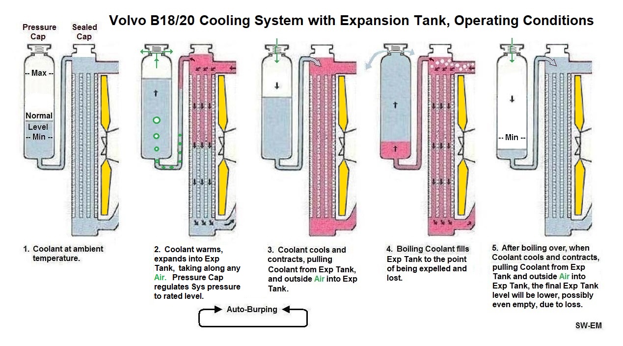
Figure 18.
Cooling System with Expansion Tank, Operating Conditions.
Late Cooling System with Exp Tank, Operating Conditions:
(Normal)
Condition 1. Cold and Stable Coolant is at ambient, no pressure in CS.
(Normal)
Condition 2. Coolant warms and expands into Expansion Tank, taking with it
minor amounts of air from the top of Rad. Pressure is
allowed to build to Pressure Cap rating, then vented. Since Coolant level
is below top of Exp Tank, none is expelled and lost.
(Normal) Condition 3. Coolant cools and contracts drawing
Coolant from Expansion Tank into CS. Where during expansion, air
was pushed into ET, Coolant is pulled back into Rad, and air is allowed to be
pulled back into Exp Tank at Pressure Cap. Author refers to this
release of air action occurring naturally between Conditions 2 and 3, as::
Auto-Burping
[It seemed like an appropriate name!]
(Abnormal)
Condition 4. Boiling Coolant fills overflow bottle, and if necessary, to the point of being
expelled and lost.
(Resulting) Condition 5. Coolant as drawn back into CS from Expansion Tank
but since some was lost, final level is lower. Air is also drawn into Exp
Tank. If ET is empty, ET, and Rad,
need to both be refilled as siphon has been broken.
Auto-Burping: Minor amounts of air which
collect in the small volume below Sealed Cap (and below the overflow tube junction)[
highest point in CS!] are expelled
as they are pushed out (at Condition 2), bubble to top of ET, but are not
pulled back in (at Condition 3)...instead, Coolant is pulled back in. This tends to keep the
CS automatically filled at the optimum level thanks to the Expansion Tank...powered
by thermal expansion/contraction!
Early Cooling System
without Exp Tank (also closed, but volume for expansion has been relocated
to inside Exp Tank!).
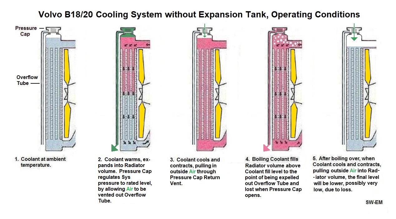
(Early) Cooling System without Expansion Tank, Operating Conditions.
Early Cooling System Operating Conditions:
(Normal)
Condition 1. Cold and Stable Coolant is at ambient, no pressure in CS.
(Normal)
Condition 2. Coolant warms and expands into the empty volume above Coolant
fill level. As pressure builds, Pressure Cap releases it precisely out
Overflow Tube to its rated level (See also:
Cooling System Operating Pressure,
below) .
(Normal) Condition 3. Coolant cools and contracts drawing
outside air back into the volume above Coolant fill level. (There is not
Auto-Burping possible without the Exp Tank! Keeping the Coolant level
correct is strictly a manual process...)
(Abnormal)
Condition 4. Boiling Coolant first fills volume above Coolant fill level,
and when this volume is full, is released by Pressure Cap, and lost.
(Resulting) Condition 5. Air is drawn back into CS from outside, but since some
Coolant was lost, final level in CS is lower. If CS has "boiled over" and
Coolant has been lost, it's advisable to check and top up Coolant level (and
"top up" is not intended to mean fill the Rad to the top, else some Coolant will
be lost due to expansion, even when no "boiling over" has occured.
Early/Late Production
Expansion Tank, Pressure Caps, and System Operating Pressures!
Note: When retrofitting an Overflow/Expansion Tank, there
were two different styles fitted from the factory (year of manufacture
dependent), see picture below, and the Pressure Caps do not
interchange! Both ETs are suitable for retrofitting, but installer
must assure that the correct associated PC is also installed!
Cooling System Operating
Pressure numbers and info (from a non-Volvo, but what I believe to be a reputable, source...dates
are approximate and can vary with country of delivery):
...to '66, no ET were fitted on CSs and PC No 87842 with a CS operating
pressure of 0.3 bar (4.4PSI).
...from '67 to '69, ET No. 676558 was fitted, with (tall) PC No. 673336,
operating pressure remaining at 0.3 bar.
...from '69 on, ET No. 686833 was fitted, system pressure was increased to 0.7
bar (10PSI), with (shorter) Cap 673233 (If retrofitting this higher
pressure set-up, pressure tests should be performed on the CS to assure it is
capable of operating at this increased pressure without leaks.)
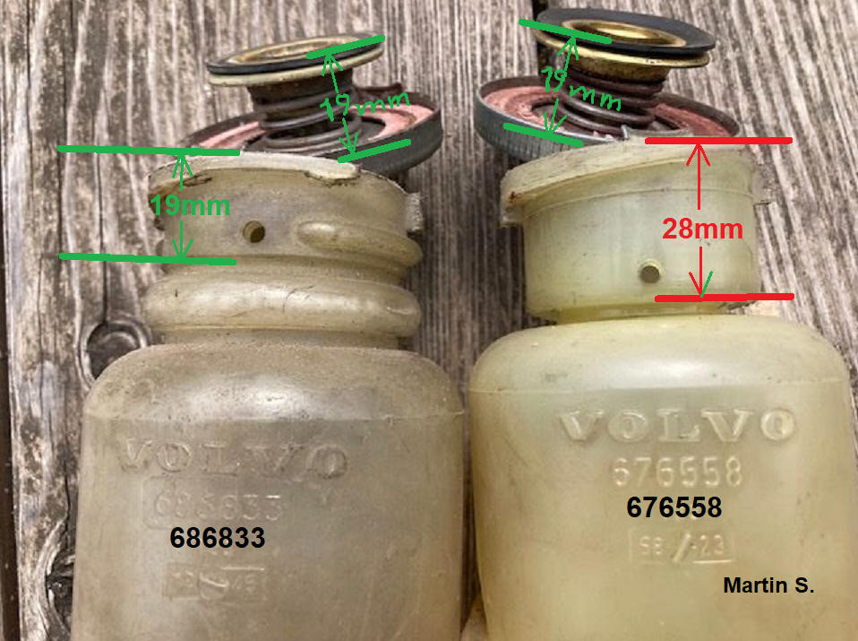
Comparing the Early (Right) and Late (Left) Expansion Tanks and
their Pressure Caps (only the late short one is shown on
both Tanks!). Note the PC on the right is too short to reach the sealing
surface of the early Tank, so if wrongly(!) installed,
the Cooling System would be effectively open to atmosphere
and no pressure could build, possibly resulting in boiling over!
[...and installer probably questioning what went wrong with the retrofit!]
Martin S. of the Volvoniacs Forum picture used with his kind permission.
-----------------
Draining
Cooling System:
A Radiator Drain and an Engine Block Drain are
provided. When replacing a
Thermostat, it is sufficient
to drain the Cooling System partially to below Tstat level to allow the service
without loss of Coolant
Draining one or two quarts from the Radiator will drop the level enough to allow
Tstat replacement without Coolant loss when opening the Tstat housing.
Cooling System Drain for the Engine Block is also provided, it is located to the
left of Oil Filter.
When Draining the System completely for the purpose of cleaning out any
particulates which have settled, the Engine Drain should also be opened, and to
assure a thorough cleaning, back-flushing with a high flow-rate garden hose is
best. Removing it completely from engine block leaves a big hole for high
volume flow-rate flushing!
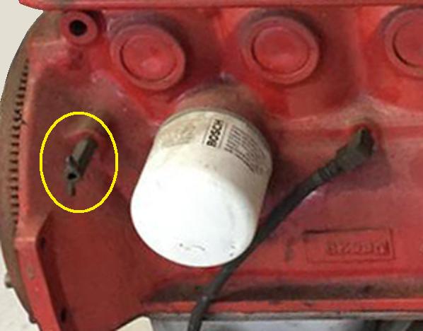
Figure 19.
Engine Block Cooling System Drain highlighted in
Yellow.
Flushing Cooling System: In
order to do the most thorough flush, both Radiator and Engine Block Drains
should be opened (Engine Block drain should even be totally removed to allow
good draining from the larger opening), and high
flow-rate garden hose be blasted into Radiator filler...I'd even blast it into
the Block drain in the reverse direction, alternating the direction of flow
several times...catch and inspect what is flushed to give an indication of what
got flushed out of the bottom of Cooling System. If necessary, filter
through a paper towel or coffee filter. Chemically active flushing additives of dilute acid, are
available to etch away and loosen crusties...
PLACEHOLDER for details and suggested brands.
If Cooling System seems to want to tend to the Hot range on the indicator,
first, verify you can rust the Indicator (Link to
Checking Temp Gauge Calibration), and once you know you can trust it,
and things are truly Hot(!), you might want to do a system flush...below is a
screen capture from a video with good explanations of what was done and why,
with pictures of what came out of a vehicle a lot younger than your old Volvo.
Good applicable info:
https://www.youtube.com/watch?v=s--5ft5YiHg
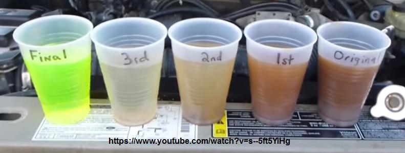
Figure 20.
Considering what came out of this Cooling System, before installing that
Electrical Cooling Fan,
you might consider a good flush and bringing your Cooling System
and Coolant
back to as-new
performance!
-----------------
Heat
Shedding of an Automotive Radiator.
My response to thread: Std or custom alloy
http://www.volvoforums.org.uk/showthread.php?p=2209661#post2209661
[...additions not part of the
original posting highlighted!]
"...yes, it's called a Radiator, and this (correctly)
suggests one mode of shedding heat, and it also (but incorrectly) suggests that
this is the predominant heat shedding mechanism.
Heat-shedding by the Radiator of a car occurs by two mechanisms: Conduction
and Radiation. [ ...note that
this is the order of effectiveness!]
Conduction...is (by indirect Contact) to the cooler
air which is pushed, pulled or otherwise directed through the high surface
area...if this flow were to stop (when Engine/Fan stop, and when we park the
car, or even when we go very slow in a traffic jam), Conduction continues, but
drops back to air Convection (this refers to density driven flow only...it
doesn't even refer to transfer of thermal energy, although that is what is
causing it). Air Convection alone (when car/engine are moving dead slow or even
stopped), air flow is simply not enough to give the cooling our cars need,
that's why the engine also drives a fan to help with this
(by moving more air than simple
Convection would), and hence a lot of
threads in the summer (when Conduction is also to much warmer air) from owners
experiencing overheating concerns.
Radiation is certainly also occurring, but it accounts for only a small
percentage of the heat shedding that is going on...to support that assertion, I
would say that a car Radiator even has the shape of a poor thermal Radiator (it
has just not been optimized for this), because most of its surface area is
pointed to other parts of itself, not away, as it would need to be if radiation
was the prime shedding mechanism...a car Radiator is optimized for Conduction
process with high surface area to airflow...unlike the space shuttle...it must
also shed lots of waste heat...but since it cannot do this by conduction to
outside air, it MUST shed by Radiation only...and the shuttle
Payload Bay doors
(see below) with their huge (and
open) surface areas are used (and optimized!) for this
(they face out and away from the craft,
and into the cold void of deep space)...if the shuttle doors
cannot swing open for some reason to radiate away waste heat, that Mission is
done and they need to come home! This has almost happened at least once!
Further, color of radiating surface does affect the efficacy,
[by varying the Emissivity] but
not enough on a car Radiator to make any kind of significant difference (again,
because Radiation is not its prime mechanism). Paint on a car Radiator is mostly
to protect metal surface, not to increase its effectiveness!
[A Radiator
painted pink would work in practical terms, just as well as one painted black]
Heatsinks on electronic equipment are often Black anodized, but also clear
(natural alu color), because here on earth, the heat sink on a piece of
electronics again works predominantly by Conduction.
In the engineering world, it would more appropriately be called a Heat-Exchanger
to prevent a biased understanding of the shedding mechanism...hope that sheds
some light...or Heat! "
[End of Posting]
More about the space shuttle...from:
http://spaceflight.nasa.gov/shuttle/reference/shutref/structure/baydoors.html
Dead Link! Sorry! See:
https://www.nasa.gov/feature/spaceflightnasagov-has-been-retired/
"Payload Bay Doors"
"The payload bay doors are
opened shortly after orbit is achieved to allow exposure of the
environmental control and life support system Radiators for heat
rejection of the orbiter's systems."
[Note: Here,
they are more correctly called Radiators!]
Further interesting reading on Thermal systems in
spaceflight:
http://pages.erau.edu/~ericksol/courses/sp300/ch10/thermal_ch10.html Another
Dead Link, Sorry. Here is what a search for "space shuttle doors shedding
heat" found:
https://books.google.com/books?id=1rofAAAAIAAJ&pg=PA9&lpg=PA9&dq=space+shuttle+doors+shedding+heat&source=bl&ots=3G9OmGd7XF&sig=ACfU3U0xk0K7FV-SdqErHiof0ODXuOUToQ&hl=en&sa=X&ved=2ahUKEwj2vpPw-8z1AhUlmuAKHWCeBFQQ6AF6BAgkEAM#v=onepage&q=space%20shuttle%20doors%20shedding%20heat&f=false
----------------
Galvanic Corrosion in the
Cooling System, and the
importance of using Coolant mix, and never Water alone (See:
Cooling System Rule No.1 ):
[File this under: You can't stop Mother nature!]
Thinking of the continuous Coolant as an electrical conductor, the
Engine Block, Radiator and Heater Core are effectively electrically
connected. The Engine Block being iron and Rad and HC being Copper or
Brass (an alloy of copper), this
connection also forms a situation of dissimilar metals in electrical contact (by
way of the liquid conductor). This is a special situation where mother nature cannot
help herself, and electrochemical action (also known as Galvanic Corrosion or
Reduction / Electrolysis) will take place.
That is why it is quite important to always fill the Cooling System with
50% Coolant mix. The commercial Coolants contain stabilizers and
anti-corrosive compounds which prevent electrical conduction and turning a
Cooling System into a chemical Battery where the least noble of the metals in
the Galvanic Couple erodes away! Referring to the Galvanic study below, it
can be seen that in the OE arrangement, the massive iron Engine Block is the least
noble (Anode) and will corrode preferentially to the more noble (Brass, Cathode) Rad
and Heater Core...any corrosion is bad, but this is not nearly as bad as if we install an Alu Rad,
because then, the situation is reversed, with the
(thin, compared to massive Engine Block*) Alu Rad being the least noble and
corroding preferentially to engine block and much more preferentially to HC.
* Massive Iron Engine Block vs. thin Alu sheetmetal Rad
determines the Cathode/Anode Ratio (CAR), and this also
affects Galvanic Corrosion. Reference:
Galvanic Corrosion
Notes - Not yet on-line!
The point to be taken from this is: It is
not particularly good a practice to install Alu Rads onto a Volvo iron block engine!...of course, the
guy selling you the shiny Alu Rad wont advise you of this...hell...he
probably doesn't know Luigi Galvani from
Giuseppe, who owns the Italian
restaurant down the street and who sings le Nozze di Figaro as he's making
pizzas!
A better solution to consider would be, to have a qualified
Radiator
shop solder you up (aka "recore") a new Rad in copper, using your original endcaps,
and new (copper!) core material they supply.
..the cost is about the same as that shiny Alu one (OK maybe more!), but the Rad can be expected to
last about as long as the factory one did, which cannot be said of the Alu
replacement Rad. Next time you're at a Rad shop, ask about Alu Rads ...they recycle a lot of them...because
it is rare that they can be repaired! Short-term Solutions
Suck! (sorry!)
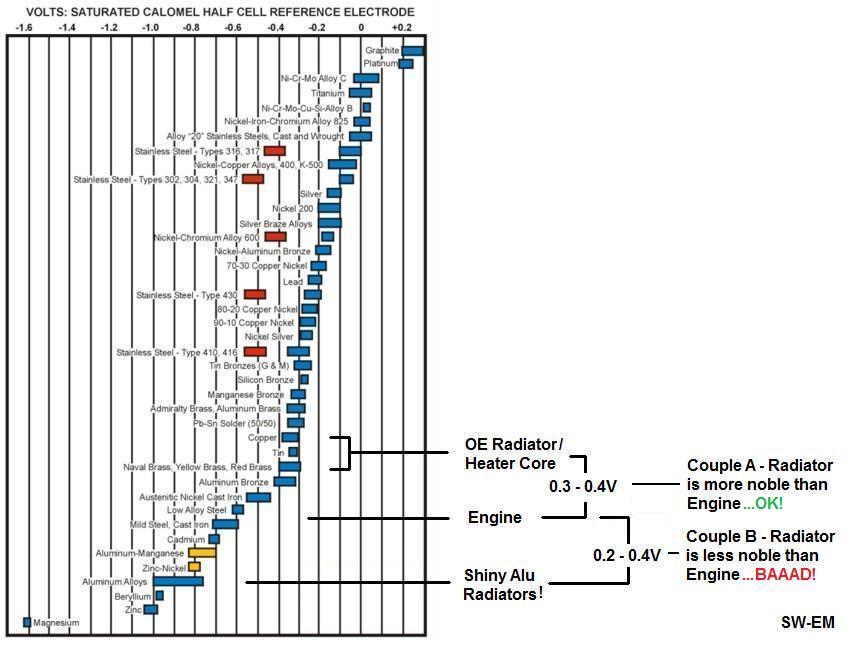
Figure 21.
Galvanic Chart marked for Copper/Brass to Iron and Aluminum.
Reference picture of what you can find behind every
Radiator shop:
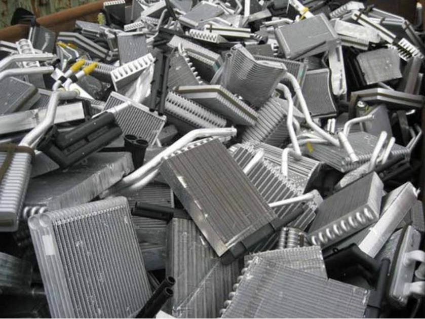
Pic Source:
https://www.ec21.com/product-details/Aluminum-Radiators-Scrap--10066783.html
On a related note, the Aluminum Cylinder Head of four
cylinder SAAB engines (also iron Block) certainly also created this kind of
electro-chemical situation. In this case, the Alu Cyl Head is again less noble...the
author knows of three separate instances, where
perforations in the Cyl Head developed, due to this Galvanic erosion, which allowed
Coolant into the intake
manifold...one can imagine the disastrous results... I don't know for a
fact if
plain water or a Coolant mix was used in these systems, but its easy to see that
for this SAAB engine, using a nonconductive, stabilized Coolant is crucially important to prevent the
potential of electrochemical erosion!
Below, a pretty impressive example of what happens to a
WaPu impeller, when connected by plain (conductive) water:
Link:
http://joeynovak.com/blog/cars/this-boys-and-girls-is-why-you-dont-put-plain-water-in-your-car/
From that page...
What happened to the Impeller?
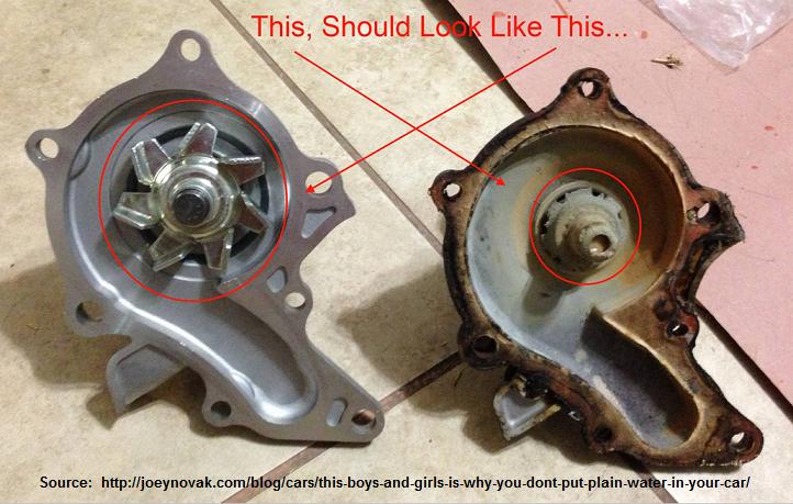
Figure 22.
New (non-Volvo!) WaPu on left, and one where plain water was used in
Cooling System for a
long time...
...that pump surely wasn't moving any Coolant!
Of note, and what might bring up a good question in the observant reader:
The Steel impeller eroded away instead of (less noble) Alu housing...what
gives...? My explanation for this is that mother nature might be
predictable, but is complex also... it is not only the relative position
on the Galvanic chart of the materials, which determines which of the two
materials undergoes reduction...but this is also affected by the Cathode
Anode Ratio (relative amount of each material) factor...and maybe
elsewhere in the Cooling Sys there was a material more noble than both, ...like
a copper Heater Core. Galvanic
Corrosion and finer the points of the CAR factor are complex subjects
which will be covered in a separate SW-EM Tech article.
----------------------
Thermal Sensing in the
Cylinder Head: Thread for B18/20 Temp Sensor is
5/8" UNF. Below,
an electrical sensor has been installed using an adapter.

Figure 23.
--------------------------------------------------------
External material
sources are attributed. Otherwise, this article is Copyright © 2007-2022. Ronald
Kwas. The terms Volvo, and Stant are used for reference only. I have no affiliation with
any of these companies other
than to try to keep their products working for me, help other enthusiasts do the
same, and also present my highly opinionated results of the use and care of their
products here. Working on the Cooling System will in some cases involve
working in close proximity to Hot or Moving components! Reminder:
Work Carefully to avoid Injuries or Damage! The information presented comes from my own
experience and carefully considered opinion, and can be used (or not!), or
ridiculed and laughed at
around the Watercooler (or worshipped!), at the readers discretion, but must
be used in conjunction with normal, cautious shop practice. As with any recipe,
your results may vary, and you are, and will always be, in charge of your own
knuckles, and future!
You are welcome to use the
information here in good health, and for your own non-commercial purposes, but
if you reprint or otherwise republish this article, you must give credit to the
author or link back to the SwEm site as the source. If you don’t, you’re just a
lazy, scum sucking plagiarist, and the Boston Globe wants you! As always, if
you can supply corrections, or additional objective information or experience, I
will always consider it, and consider working it into the next revision of this
article...along with likely the odd metaphor and possibly wise-a** comment.