
Coolant Distribution Pipe Detail.
Temperature Sensing Bulb of Temp Indicating System is located at far end of cylinder Head from Water Pump.
Coolant Distribution Pipe Notes
Sept 2003, R. Kwas, changes
on-going
-----------------------------
Links
Blocked Coolant Distribution Tube in Cylinder Head
Reference information: CDP Shape and Retention
-----------------------------
The internal Coolant Distribution Pipe in the B18/20 motors, is a brass tube, which routes (the entire!) Coolant output from Water Pump to Cylinder Head, and distributes it by way of slots at each cylinder, and in this way assures equally effective cooling from front to back cylinders and without preference to the cylinders nearer the WaPu. Although completely hidden behind one of the Freeze Plugs, so not obvious, the Pipe must be clear and free to do this without problems. The best time to check it is at rebuild time, when Cylinder Head is removed from engine and access is good, but it can also be removed for checking while Cylinder Head is installed.
Coolant Distribution Pipe Detail.
Temperature Sensing Bulb of Temp
Indicating System is located at
far end of cylinder Head from Water Pump.
-----------------------------------------
All subsequent pictures were kindly supplied by Volvoniac Forum member: er ka (aka Ronald K. ...no, not me!) and used with his permission.
A Temp indication such as this is on the high side with little margin...any higher than this would be cause for concern! This naturally presumes accuracy of Temp Indicator has been checked. See: Temperature Gauge Notes, Checking Calibration

Before Temp reading that's on the high side.
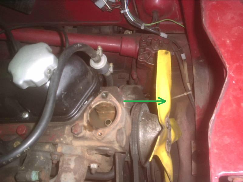
With Cylinder Head in place, Coolant Dist Pipe is behind smaller of the two
forward facing Freeze Plugs.
Pipe can be withdrawn, highlighted in
Green, even with
Grill
in place, but Radiator needs to be removed.

After removal of the right (smaller) Freeze Plug, end of Brass Pipe is visible,
highlighted in Green.
Pipe
should not be loose in its location, but have edges peened over in order to lock
it into place and prevent it from rotating or otherwise moving out of position.
Cross-section of pipe is rather key-hole shaped, so that under normal
conditions, it only locates into the head in one axial orientation, with
distribution slots in a preferred position (toward combustion chambers).
See also: Reference information:
CDP Shape and Retention

Removal of Pipe with a needle-nose pliers, highlighted in
Blue. Remove gently!
Pipe is thin-walled brass!

Coolant Distribution Pipe after removal.
Distribution slots (of differing sizes, Left is Cyl 1 end) for each cylinder are apparent.
These should be checked
for and cleared of any crystalline sclerosis similar to what is often found in
Radiator!
---------------------------
Report on a Blocked Coolant Distribution Tube in Cylinder Head which caused a mysterious overheating! [B16, but enough similarities to B18/20, to be worth a look! I had a hard time finding this, so I'll save the reader the trouble and simply include a screenshot here.] http://cvolvo.com/Central/AMAZON/eleven-twelve.html

---------------------------
Additional:
With the European heat wave of the summer of 2003, a number of Volvoniacs experienced higher than typical hot running vehicles. Even with an otherwise well functioning Cooling System, those high temperature can result in a B18/20 getting rather hot under the collar while running in slow (or even worse: non-moving) traffic! The Temp indicated can become concerning! That's when owners start thinking about installing Electrical Cooling Fan, but that is another subject covered under Cooling System [not yet on-line].
Distribution Pipe Modification: The openings/slots in the pipe obviously need to be clear and unobstructed by crystallized cooling system corrosion, and it is good practice to remove inspect and clean Distribution Pipe at engine rebuilding time! In extreme cases (like racing), slots can be opened to increase flow. It must be stressed here that the entire list of things to check should be performed, to assure good normal Cooling System function before considering such modifications...Cooling System must be in otherwise good working condition!
Er ka took the situation to hand and went ahead with modification to his Coolant Distribution Pipe.

Coolant Pipe After enlargement of Distribution holes. Left is Cyl 1 end.
These were approximately doubled in cross-sectional area. See text for
dimensions.

That's better, and apparently the typical Temp Indication After opening distribution slots shows that the
modification is quite effective.

er ka's gorgeous 544Cabrio...and with a modified Distribution pipe, running cool as a cuke!
Info from er ka:
Ronald K. <xxxxxxxxxxxx@web.de> [My Translation and comments. Ron]
Tuesday, September 09, 2003 9:14 AM
Hallo Ron,
>
> wie versprochen, ein kurzer Bericht über die Optimierung des Umlaufrohres.
>
> Folgende Schritte: Removal
Steps:
>
>
> Kühler leer laufen lassen und ausbauen,
Drain Coolant, remove Radiator
> Thermostatgehäuse aufschrauben und Thermostat entnehmen,
Remove Tstat Housing and Tstat
> Froststopfen demontieren Remove
Freezeplug ( drill Freezeplug, screw in a sliding Hammer, and give it a couple
of pull impacts)
> Umlaufrohr mit einer Spitzzange herausziehen
Remove Pipe with a needle nose pliers
> Kühlergrill muss nicht demontiert werden, dass Umlaufrohr lässt sich so
> entnehmen, es ist etwas kniffelig, aber es geht
Grill does not need to be removed.
Its tricky, but there's enough room.
> Die Originalschlitze von vorne nach hinten gesehen, hatten die Maße:
[ Initial dimensions of Distribution
slots, front to back.]
>
> 1.) 20,9 x 4,2
> 2.) 17,1 x 4,2
> 3.) 14,0 x 4,2
> 4.) 14,0 x 4,2
>
> und wurden geändert in:
[ Dimensions of slots after enlargement. Note: Er ka gives no
supporting info as to how these dimensions were arrived at. ]
>
> 1.) 40,9 x 8,2
> 2.) 37,1 x 8,2
> 3.) 34,0 x 8,2
> 4.) 34,0 x 8,2
>
>
> Wenn das Umlaufrohr demontiert ist, kann man das Kühlsystem in
With pipe removed it's possible to do a
good flush in the reverse direction with a hose as inside of Head is open and
accessible
> Gegenlaufrichtung mit dem Schlauch gut durchspülen, da der Kopf innen frei
> liegt.
>
> Montage: Installation
>
> Umlaufrohr einsetzen, geht nur in einer Position, verstemmen und neuen
Insert pipe, this is only possible in
one position, displace metal to secure in place
> Froststopfen in zuvor gesäuberten Sitz einpressen (geht mit einem Stück Holz
Replace Freezeplug into cleaned location
(use gasket sealer) securing Freezeplug with a piece of wood works well
> recht gut)
>
> Thermostat und Gehäuse montieren, Kühler montieren und füllen...... fertig
Replace Tstat and its Housing, install
Radiator, refill system, done!
>
> Noch ein Tipp: More Tips
>
> Das Vergrößern der Schlitze im Umlaufrohr funktioniert sehr gut mit einem
A center drill and Dremel with cut-off
disc work well to enlarge distribution holes
> Zentrierbohrer und Dremel mit Trennscheibe.
>
> VORSICHT: Das Rohr ist dünnwandig und relativ weich.
CAUTION, the pipe is thin walled brass
and soft!
>
> Der Umbau nahm bei mir ca. 1,5 Stunden in Anspruch
Work took me about an hour and a half
> Mittlerweile habe ich auch den 2. B20 Motor umgebaut und bin vom Ergebnis
I have since also made this modification on a B20 and am convinced by the result
> überzeugt.
>
> Im Anhang findest Du ein paar Bilder, ich hoffe Du kannst Sie verwenden,
I have attached a few pictures, I
hope you can use them
> leider kann ich besser schrauben als fotografieren.
I can wrench better than I can take
pictures
>
>
> Happy swedish motoring
> Ronald (er ka)
---------------------------
Reference information:
Coolant Distribution Pipe is essentially round in cross-section, but somewhat
formed at the Tstat end, such that it is an interference fit in the Head casting
and can be slightly deformed to remain in place rotationally, and this is
supposed to be with distribution slots pointing toward exhaust valve seats.
A slight rattling might be detectable when Head is off an engine. This not
unusual as the Cyl 4 end of the pipe is simply in its clearance and not secured
there particularly well...but when Head is in service and filled with coolant,
pipe is "padded" by surrounding coolant...what is important is that the pipe be
oriented correctly on installation, and deformed to remain in that position, so
that distribution of coolant and flow is as designed and intended.
Two heavily touched up pictures of a cylinder head, but with Freeze Plugs removed so that CDP is visible in-situ.
 |
 |
| Cylinder 1 (open) end of Coolant Dist Pipe. Source: | Cylinder 4 (closed) end of Coolant Dist Pipe. Source: ? |
---------------------------
Another example of CDP modification, also from the Volvoniacs:

CDP with stock sizes indicated on top, and a modified one below. Again,
the larger size and locations were arrived at by trial and error of some
experienced individuals, but no specific other supporting data is presented.
Source:
http://www.networksvolvoniacs.org/index.php/Wasserf%C3%BChrungsrohr_B18_/_B20_modifizieren
Author's calculations with the purpose of comparing the original factory cross-section of the feed-slots compared to the pipe cross-sections, and that of the increased, ...my notion is that as the slot cross-section of the slots nearer the WaPu approach that of the pipe, the downstream slots will get starved to some extent, so while Cyls 1 and 2 get increased Coolant from the increased slots, Cyl 3 and 4 get less and will run hotter as a result...I consider this as undesirable!
CDP Diameter (estimated) 15mm, so pipe cross sectional area is = 1772mm = (3.1415 (7.5)2) = π X R2
Original
After opening slots
(erkas result)
21 X4.2
21 +15 X 5
40.9 X 8.2
+17 X 4.2
17 + 16 X 5
37.1 X8.2
+14X4.2
14 + 15 X5
34 X 8.2
+14X4.2
14 + 14 X5
34 X 8.2
218.42mm
6352mm
11962mm
Observation and Opinion (not conclusion!): The total of original total cross-sectional area of feed slots is about 25% over that of the pipe. whereas the Volvoniacs modification makes it about 3.5 times the original (and this has been shown to yield good results), and the erka mod makes it whopping 6.7 times. I suspect that in the case of the erka mods, that Cyls 3 and 4 are indeed being at least partially starved...so if someone was considering these mods, I'd recommend the more conservative Volvoniacs dimensions, and not larger erka mods, but again, this is strictly the author's carefully considered opinion!
Engine builders who make such mods are invited to share details and their experience with the author. Please e-mail!
---------------------------
External sources attributed. This information is Copyright © 2003-2017 Ronald Kwas, with input contribution by Ronald Klein. The term Volvo is used for reference only. I have no affiliation with this company, other than to try to keep its cars working for me, and cool and to help other enthusiasts to do the same. The results and information presented here are my own experience, and carefully considered opinion, and can be worshipped or laughed at and ridiculed as you see fit. As with any recipe, your results may vary, and you are, and will always be, in charge of your own knuckles, and future!
As always, if you can supply additional objective info or practical experience, I’d appreciate hearing it, and will consider working it in to the next rewrite of this article...along quite possibly with the odd wise-a** comment, if I can possibly work that in. You are welcome to use the information here in good health, and for your own noncommercial purposes, but if you reprint or otherwise republish this article, you must give credit to the author or link back to the SwEm site as the source. If you don’t, you’re just a lazy, scum sucking plagiarist...so the Washington Post wants you!
